
Clock configuration

a clock configuration and clock technology, applied in the field of clock configuration, can solve the problems of less accurate reference oscillators for real-time clocks than reference oscillators, and achieve the effects of faster boot, flexible operation, and slow boot speed

Active Publication Date: 2012-12-25
ICERA INC
View PDF12 Cites 0 Cited by
  • Summary
  • Abstract
  • Description
  • Claims
  • Application Information

AI Technical Summary

Benefits of technology

[0009]Thus by providing for discovering the reference frequency in the boot, the present invention is more flexible and “future-proof” in terms of the choice of reference oscillator. This advantageously allows customers a choice in the reference oscillator they use without the need to specifically tailor the circuit in that respect for each customer. It can also allow a customer to be able to change their design at a later stage.
[0015]Thus the boot code can advantageously support different configurations of clock circuitry, e.g. different configurations of PLL, depending on the discovered reference frequency. This advantageously allows customers a choice in the reference oscillator they use as a reference for their clock, again without having to specifically tailor the circuit. For example, it may allow the chip's main frequency to be configured without the need to blow fuses, and allow flexibility in the board design and choice of main crystal.
[0017]Discovering the frequency will result in a slightly slower to boot but is more flexible, whilst simply specifying the frequency in the fuses will allow a faster boot but is less flexible. Given this trade-off, it is therefore advantageous to provide the circuit with different modes in order to allow a choice between the two possibilities.

Problems solved by technology

Reference oscillators for real-time clocks tend to be less accurate than the reference oscillators for clocking the circuit, particularly for clocking the processor.

Method used


Image

  • Clock configuration
  • Clock configuration
  • Clock configuration

Examples


Embodiment Construction

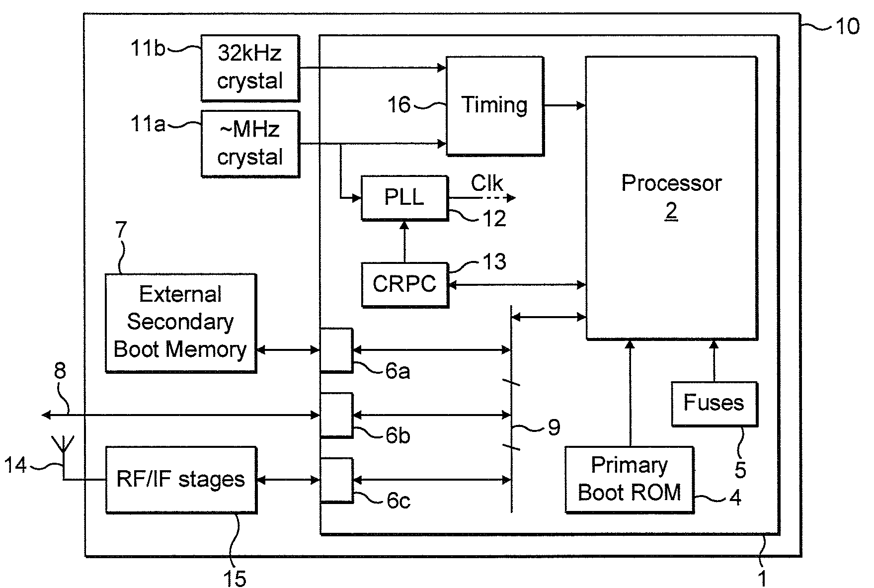
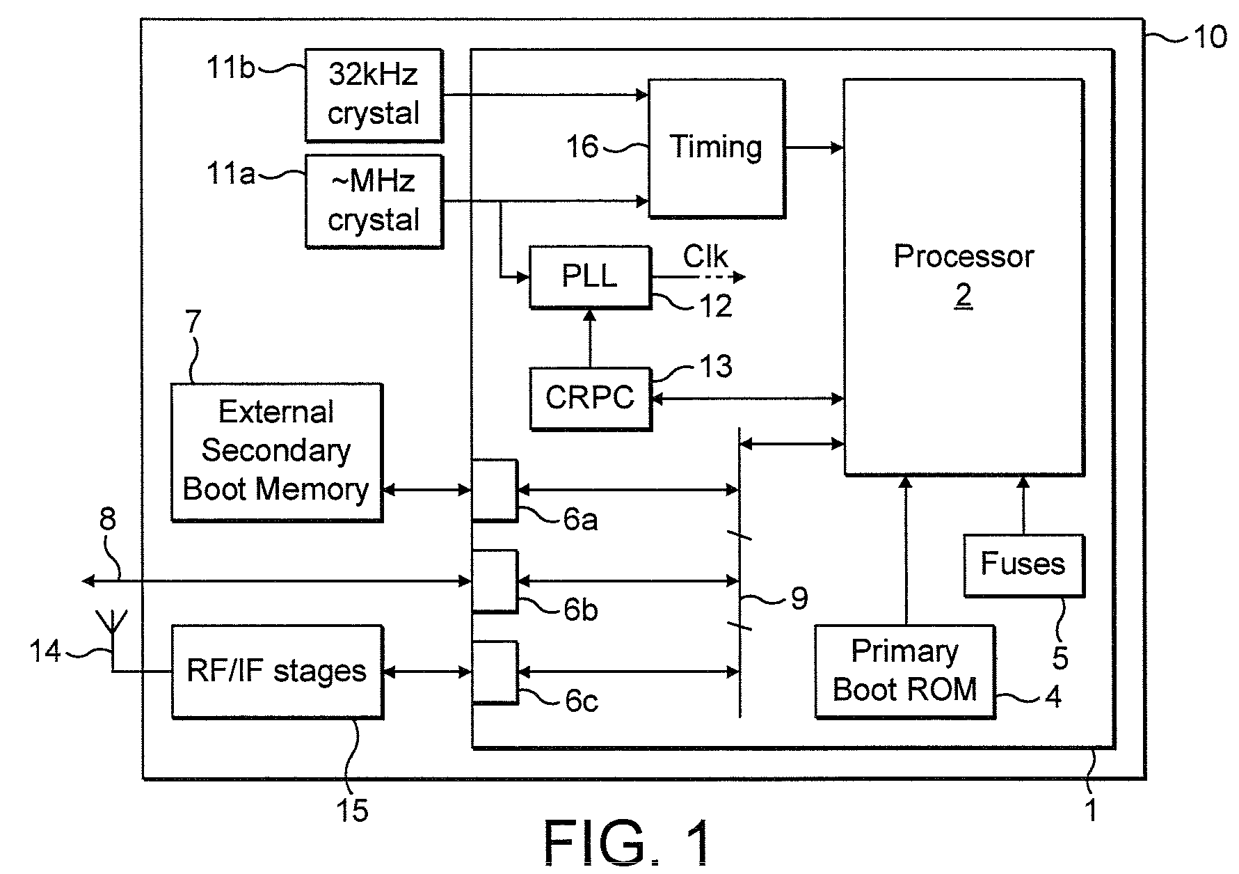
[0033]An example application of the present invention is now described with reference to FIG. 1 which shows schematically a user device 10, preferably a mobile terminal or other wireless device such as a mobile phone, laptop wireless data card, PDA, etc. The device 10 comprises an integrated circuit 1 having a processor 2 configured as a software modem or “soft modem” for communicating over a wireless cellular network. The principle behind software modem is to perform a significant portion of the signal processing and associated functions required for the wireless communications in a generic, programmable, reconfigurable processor, rather than in dedicated hardware.

[0034]The integrated circuit 1 comprises an RF interface 6c, and the device 10 comprises front-end hardware 15 coupled to the RF interface 6c and at least one antenna 14 coupled to the front-end 15. Preferably, the processor 2 is programmed as a soft baseband modem, with the front-end 15 comprising the RF (radio frequency...


PUM


Abstract

A circuit and method for determining the frequency of a first oscillating reference signal generated by a first reference oscillator. The circuit comprises: a second reference oscillator arranged to generate a second oscillating reference signal having a known frequency, a boot memory storing boot code comprising clock configuration code, and a processor coupled to the boot memory and the second reference oscillator. The processor is arranged to execute the boot code from the boot memory upon booting, wherein when executed the clock configuration code operates the processor to determine the frequency of the first reference signal by reference to the second reference signal.

Description

PRIORITY CLAIM[0001]The present application claims the priority of Great Britain Patent Application No. GB 0807924.6 filed Apr. 30, 2008.FIELD OF THE INVENTION[0002]The present invention relates to a method and apparatus for configuring clock circuitry.BACKGROUND OF THE INVENTION[0003]An electronic circuit having a processor will require clock circuitry such as a phase-locked loop (PLL) which generates a clock signal for the circuit. The clock signal may subsequently be divided and / or branched multiple times throughout the circuit, but the PLL is usually the master source of the clock signal.[0004]A PLL generates the clock signal by reference to a reference oscillator, typically a crystal oscillator mounted on the same board as the processor chip. For a processor, the reference oscillator frequency is typically of a lower order of magnitude than the clock frequency to be generated.[0005]The PLL works by branching off its output clock signal and dividing the frequency by the desired ...

Claims


Application Information

Patent Timeline
Patent Type & Authority Patents(United States)
IPC IPC(8): G06F1/00G06F9/00
CPCG06F1/04G06F9/4401G06F1/08G06F1/14
Inventor MANGNALL, JONCUMMING, PETER
Owner ICERA INC
Learn More