
NMR Probe

a technology of nuclear magnetic resonance and probe, which is applied in the direction of magnetic measurement, instruments, measurement devices, etc., can solve the problems of limited tuning range that can be handled, 219 cannot handle the large number of nuclear species, and cannot be continuously changed, so as to achieve the effect of changing the tuning range of the detection circui

Active Publication Date: 2016-08-11
JEOL LTD
View PDF2 Cites 8 Cited by
  • Summary
  • Abstract
  • Description
  • Claims
  • Application Information

AI Technical Summary

Benefits of technology

The present invention is about an NMR probe which allows for changing the characteristics of its electronic circuit without affecting the surrounding environment. This is achieved by changing an additional member in the sub space of the probe while maintaining the peripheral environment of the basic electronic circuit in a vacuum state. The additional member can be a capacitor or any other active or passive element. The NMR probe has a double structure, with the primary space and the sub space being isolated from each other, and the cooling mechanism is used to maintain the basic electronic circuit in a connected state. The sub space can be partially opened to the atmosphere through a gate and a plug to prevent direct flow-in of atmospheric air. The technical effect of this invention is that it allows for flexibility in changing the characteristics of the electronic circuit without affecting the environment, while maintaining the vacuum state of the primary space.

Problems solved by technology

In the method described in U.S. Pat. No. 7,701,219, because the tuning range is changed using a limited number of capacitors, the tuning ranges that can be handled are limited.
For example, a problem may arise in that the tuning range cannot be changed continuously, and the tuning range is discretely set.
However, when the number of nuclear species to be observed is increased, the method described in U.S. Pat. No. 7,701,219 cannot handle the large number of nuclear species.
For example, the number of nuclear species is large for inorganic substances, and thus, with the method of switching among a limited number of capacitors, it may not be possible to set a tuning range corresponding to the nuclear species to be observed.
However, a problem arises in that, as the number of capacitors is increased, the size of the NMR probe housing the capacitors is also increased.
In addition, in order to handle a larger number of nuclear species, the number of capacitors to be provided becomes enormous, which is not practical.
As described, with the method of using a limited number of capacitors, it is difficult to set a tuning range corresponding to an arbitrary nuclear species.

Method used


Image

  • NMR Probe
  • NMR Probe
  • NMR Probe

Examples


first preferred embodiment

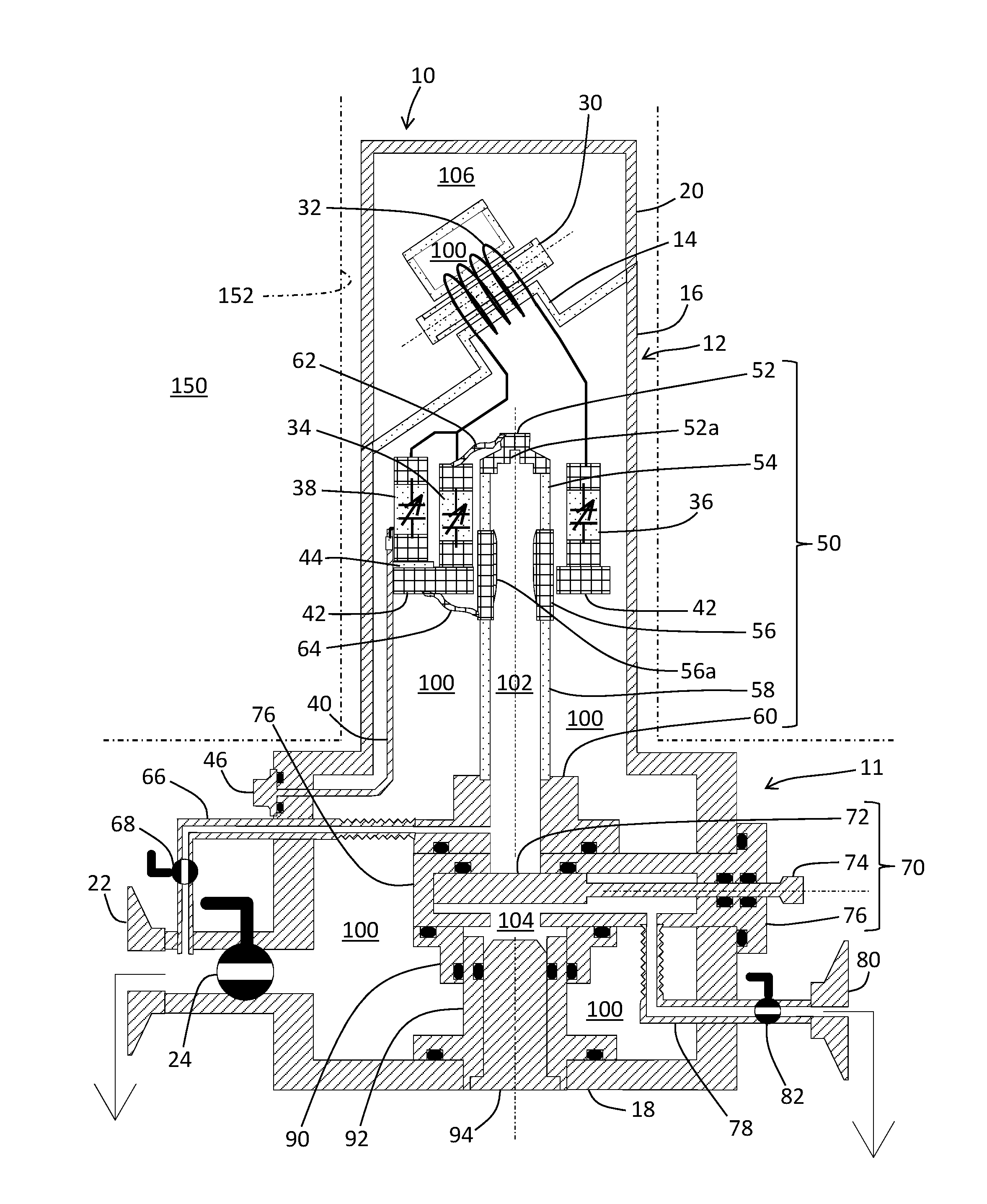
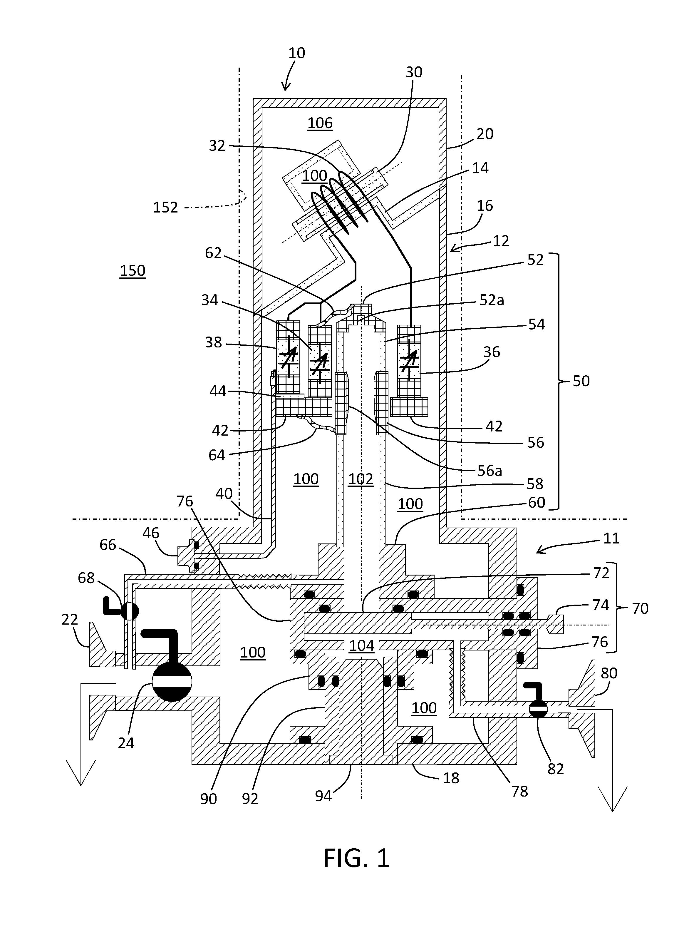
[0043]FIG. 1 shows an NMR probe (detection system cool-type NMR probe) according to a first preferred embodiment of the present invention. This NMR probe is used, for example, when analyzing a molecular structure of a sample. In the present embodiment, the sample may be any of solid, gas, and liquid.

[0044]The NMR probe according to the first preferred embodiment comprises an insertion section 10 and a lower unit 11. The insertion section 10 has an overall tubular shape extending in a vertical direction, and is inserted into a bore 152 of a static magnetic field generation apparatus 150. The NMR probe comprises an outer container 12, an inner container (container including a tube body 50) provided in the outer container 12, and a tank circuit (detection circuit) having a transmission and reception coil 32. A space inside the outer container 12 is separated by the inner container into a primary airtight chamber 100 and a sub airtight chamber (an upper airtight chamber 102 and a lower ...

second preferred embodiment

[0134]Next, an NMR probe according to a second preferred embodiment of the present invention will be described with reference to FIG. 14. FIG. 14 shows an example of the NMR probe according to the second preferred embodiment. In the NMR probe according to the second preferred embodiment, two tube bodies are placed spatially parallel to each other. With such a configuration, it becomes possible to add two additional members to two locations in the tank circuit from the outside of the NMR probe.

[0135]The NMR probe according to the second preferred embodiment comprises an insertion section 200 and a lower unit 202. The insertion section 200 has an overall tubular shape extending in the vertical direction, and is inserted in the bore 152 of the static magnetic field generation apparatus 150. The NMR probe includes an outer container 212, an inner container (container including a tube body 250) provided in the outer container 212, and a tank circuit (detection circuit) having a transmiss...


PUM


Abstract

An inner container including a tube body is provided in an outer container. With this structure, the inside of the outer container is separated into a primary airtight chamber and a sub airtight chamber (upper airtight chamber and lower airtight chamber). A detection circuit is placed in the primary airtight chamber. The detection circuit is a tuning and matching circuit having a transmission and reception coil serving as an NMR detection element and a variable capacitor. An additional member including an additional element such as a capacitor is inserted into the upper airtight chamber, and the additional member is set on a top terminal mounting member and a bottom terminal mounting member. With this structure, the additional element is electrically connected to the detection circuit and a characteristic of the detection circuit is changed.

Description

PRIORITY INFORMATION[0001]This application claims priority to Japanese Patent Application No. 2015-022651 filed on Feb. 6, 2015, which is incorporated herein by reference in its entirety.BACKGROUND[0002]1. Technical Field[0003]The present invention relates to an NMR (Nuclear Magnetic Resonance) probe, and in particular, to a technique for changing a characteristic of an electronic circuit in an NMR probe.[0004]2. Related Art[0005]In nuclear magnetic resonance (NMR) apparatuses, an NMR probe (an NMR signal detection probe) is placed along with a sample within a superconductive magnet that generates a static magnetic field. The NMR probe has a transmission and reception coil. The transmission and reception coil has functions to apply a varying RF (radio frequency) magnetic field to the sample during transmission, and to detect an NMR signal of the sample during reception. Because a resonance frequency differs depending on a nuclear species to be observed, in a sample measurement, a hi...

Claims


Application Information

Patent Timeline
Patent Type & Authority Applications(United States)
IPC IPC(8): G01R33/36G01R33/34
CPCG01R33/30G01R33/307G01R33/31G01R33/3621G01R33/3635G01R33/3403G01R33/3628
Inventor MIZUNO, TAKASHITAKEGOSHI, KIYONORIFUJIOKA, KOJI
Owner JEOL LTD
Learn More