High-frequency module

a high-frequency module and high-frequency technology, applied in transmission, multiple-port network, electrical equipment, etc., can solve the problems of harmonic distortion in the diode in the circuit that is not caused, leakage of transmission signal, etc., to suppress harmonic distortion and improve isolation, the effect of reducing the occurrence of harmonic distortion

Active Publication Date: 2012-12-18
MURATA MFG CO LTD
View PDF21 Cites 2 Cited by
  • Summary
  • Abstract
  • Description
  • Claims
  • Application Information

AI Technical Summary

Benefits of technology

[0008]To overcome the problems described above, preferred embodiments of the present invention provide a high-frequency module capable of improving the isolation between the high-frequency signal circuit and the low-frequency signal circuit as compared to the related art to suppress the occurrence of harmonic distortion and the degradation of harmonic characteristics.
[0010]With the above-described configuration, it is possible to prevent leakage of a signal from the second signal circuit into the first signal circuit so as to suppress the occurrence of the harmonic distortion and the degradation of the harmonic characteristics in the first signal circuit, which are caused by the leakage of the signal from the second signal circuit.
[0012]With the above-described configuration, when the first and second switch elements are turned on, leakage of a signal from the second signal port into the first signal port in the first signal circuit can be effectively suppressed. When the first and second switch elements are turned off, the series resonance can be produced between the first inductor, the first capacitor, and the second inductor to suppress leakage of a signal from the second signal circuit into the first signal circuit. Accordingly, it is possible to assign different functions to the first inductor between when the first and second switch elements are turned on and when the first and second switch elements are turned off, thus enabling a decrease in the number of elements and a reduction in size of the high-frequency module.
[0014]With the above-described configuration, it is possible to cause the first capacitor and the second inductor to function as the matching circuit for the filter element, thus enabling a decrease in the number of elements and a reduction in size of the high-frequency module.
[0016]With the above configuration, it is possible to achieve a reduction in size of the second inductor and the first capacitor in the first signal circuit defining a high-frequency signal circuit.
[0017]According to preferred embodiments of the present invention, the series resonance between the first inductor, the first capacitor, and the second inductor in the first signal circuit can be used to suppress leakage of a signal from the second signal circuit into the first signal circuit. Accordingly, the isolation between the first signal circuit and the second signal circuit is improved so as to suppress an occurrence of the harmonic distortion and degradation of the harmonic characteristics.

Problems solved by technology

If sufficient isolation is not ensured by the diplexer, there is a problem in that a transmission signal leaks from the circuit that is being used to the circuit that is not being used.
Specifically, harmonic distortion can be caused in the diode in the circuit that is not being used, particularly, in the diode provided in the signal path for transmission signals to degrade the harmonic characteristics of the high-frequency module.

Method used


Image

  • High-frequency module
  • High-frequency module
  • High-frequency module

Examples


Embodiment Construction

[0026]An example of the configuration of a high-frequency module according to a first preferred embodiment of the present invention will be described below.

[0027]The high-frequency module according to the first preferred embodiment is preferably used, for example, in a front end portion of a mobile phone and preferably supports four communication systems for a global system for mobile communication (GSM) 850 MHz band, a GSM 900 MHz band, a GSM 1800 MHz band, and a GSM 1900 MHz band.

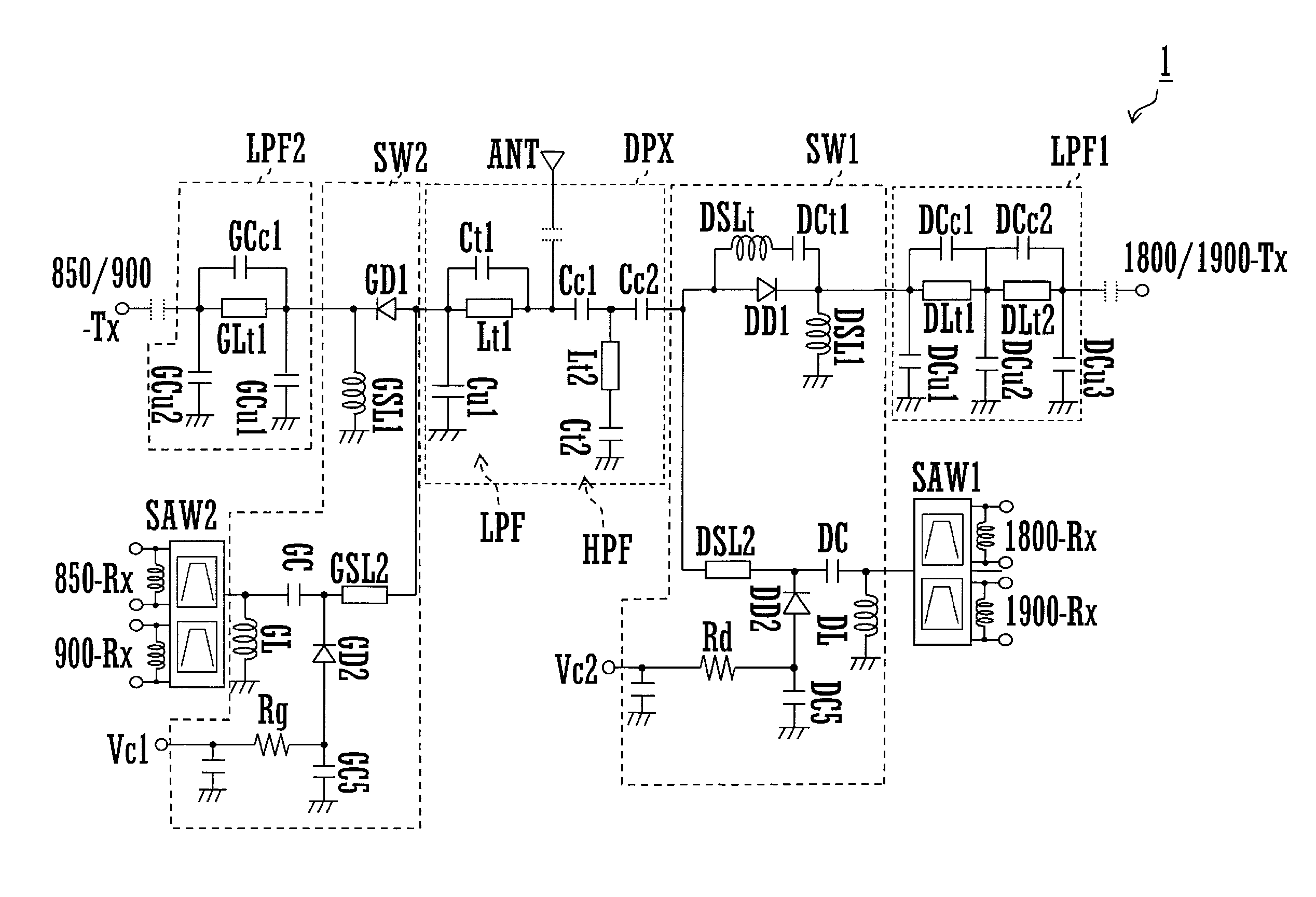
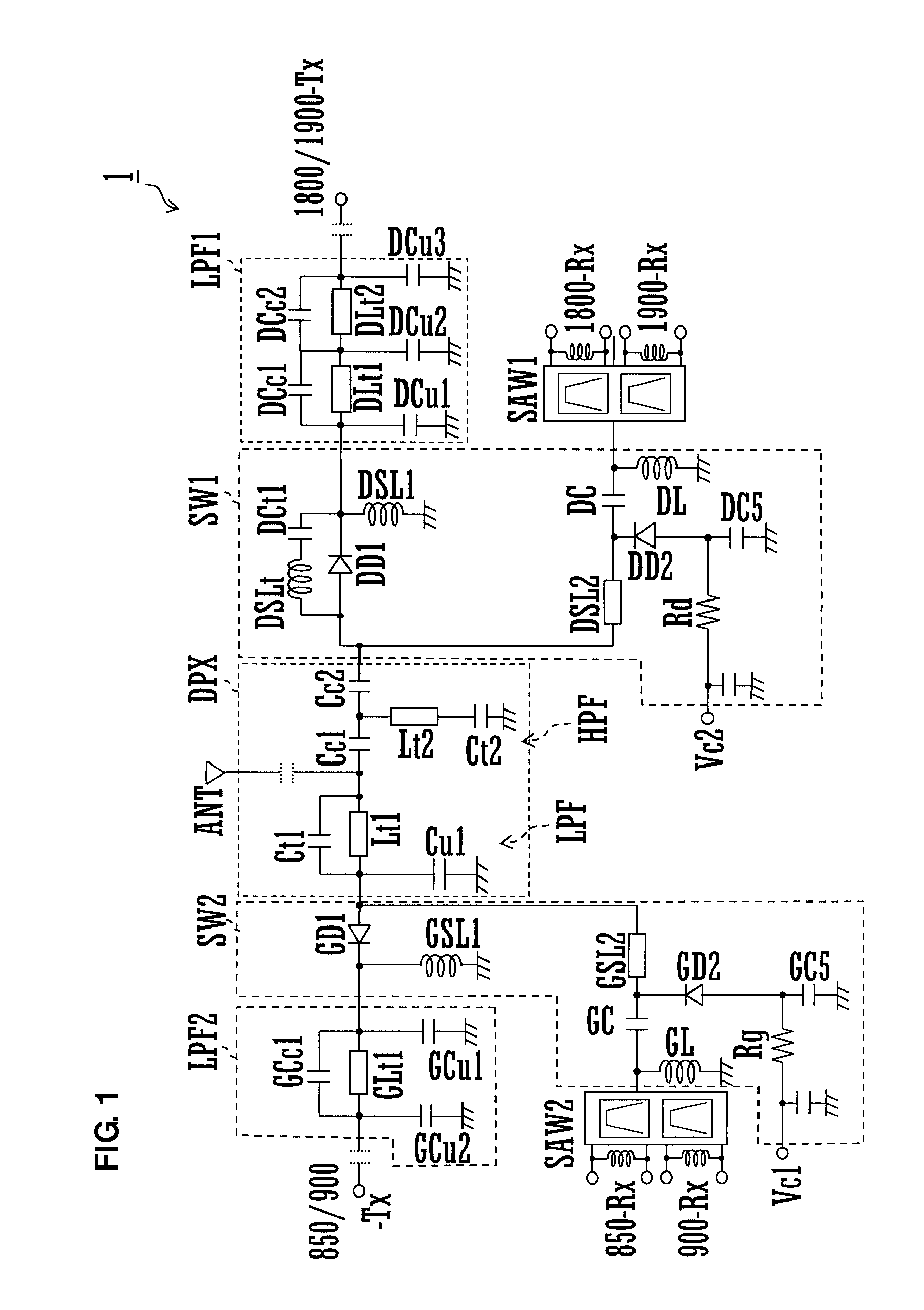
[0028]FIG. 1 is a schematic circuit diagram of a high-frequency module 1 according to the first preferred embodiment.

[0029]Referring to FIG. 1, the high-frequency module 1 includes a diplexer DPX, switch circuits SW1 and SW2, low pass filters LPF1 and LPF2, and surface acoustic wave filters SAW1 and SAW2. The high-frequency module 1 includes an antenna port ANT, signal ports 1800 / 1900-Tx, 1800-Rx, 1900-Rx, 850 / 900-Tx, 850-Rx, and 900-Rx, and control ports Vc1 and Vc2 as external connection ports.

[0030]The...


PUM


Abstract

A high-frequency module includes at least first and second signal circuits that are each connected between a common antenna port and at least first and second signal ports. The first signal circuit includes a first inductor connected in series between the antenna port and the first signal port, a first capacitor connected in series between the first inductor and the first signal port, and a second inductor connected in shunt between the first capacitor and the first signal port. Series resonance is produced between the first inductor, the first capacitor, and the second inductor at a frequency within the frequency band of a target signal of the second signal circuit.

Description

BACKGROUND OF THE INVENTION[0001]1. Field of the Invention[0002]The present invention relates to a high-frequency module used in, for example, a front end portion of a mobile phone.[0003]2. Description of the Related Art[0004]High-frequency modules that support multiple frequency bands use a single antenna for multiple communication systems using different frequency bands (for example, see Japanese Unexamined Patent Application Publication No. 2001-292073).[0005]The high-frequency module disclosed in Japanese Unexamined Patent Application Publication No. 2001-292073 includes a diplexer connected to the antenna. A high-frequency signal circuit is isolated from a low-frequency signal circuit by the diplexer. The high-frequency signal circuit and the low-frequency signal circuit each include a switch circuit. The switch circuit includes a diode connected in series to a signal path for transmission signals and a diode connected in shunt to a signal path for reception signals. Switching ...

Claims


Application Information

Patent Timeline
Patent Type & Authority Patents(United States)
IPC IPC(8): H01P1/10H03H7/46H03H7/075H04B1/44
CPCH03H7/465H04B1/44H03H9/725
Inventor UEJIMA, TAKANORI
Owner MURATA MFG CO LTD
Why Eureka
Try Eureka