
Photovoltaic module

a photovoltaic module and photovoltaic technology, applied in the direction of solar thermal energy generation, branching pipes, solar heating energy, etc., can solve the problems of lowering workability drawback, and achieve the effect of facilitating handling

Active Publication Date: 2012-12-11
SANYO ELECTRIC CO LTD
View PDF7 Cites 5 Cited by
  • Summary
  • Abstract
  • Description
  • Claims
  • Application Information

AI Technical Summary

Benefits of technology

The invention is a photovoltaic module that prevents deformation of the corners during assembly and has good workability. The module includes a frame with a hollow structure and a fit-engagement portion that fixes the module body. The frame is designed with a mounting portion that is press-inserted with a press-insertion member from another frame. This prevents deformation of the outer frame and increases production efficiency. The frame also has a chamfered corner that reduces pain or discomfort when handled.

Problems solved by technology

When the gap 855 is produced, an adjustment work is required for closing the gap 855, resulting in a drawback of lowered workability.

Method used


Image

  • Photovoltaic module
  • Photovoltaic module
  • Photovoltaic module

Examples


first embodiment

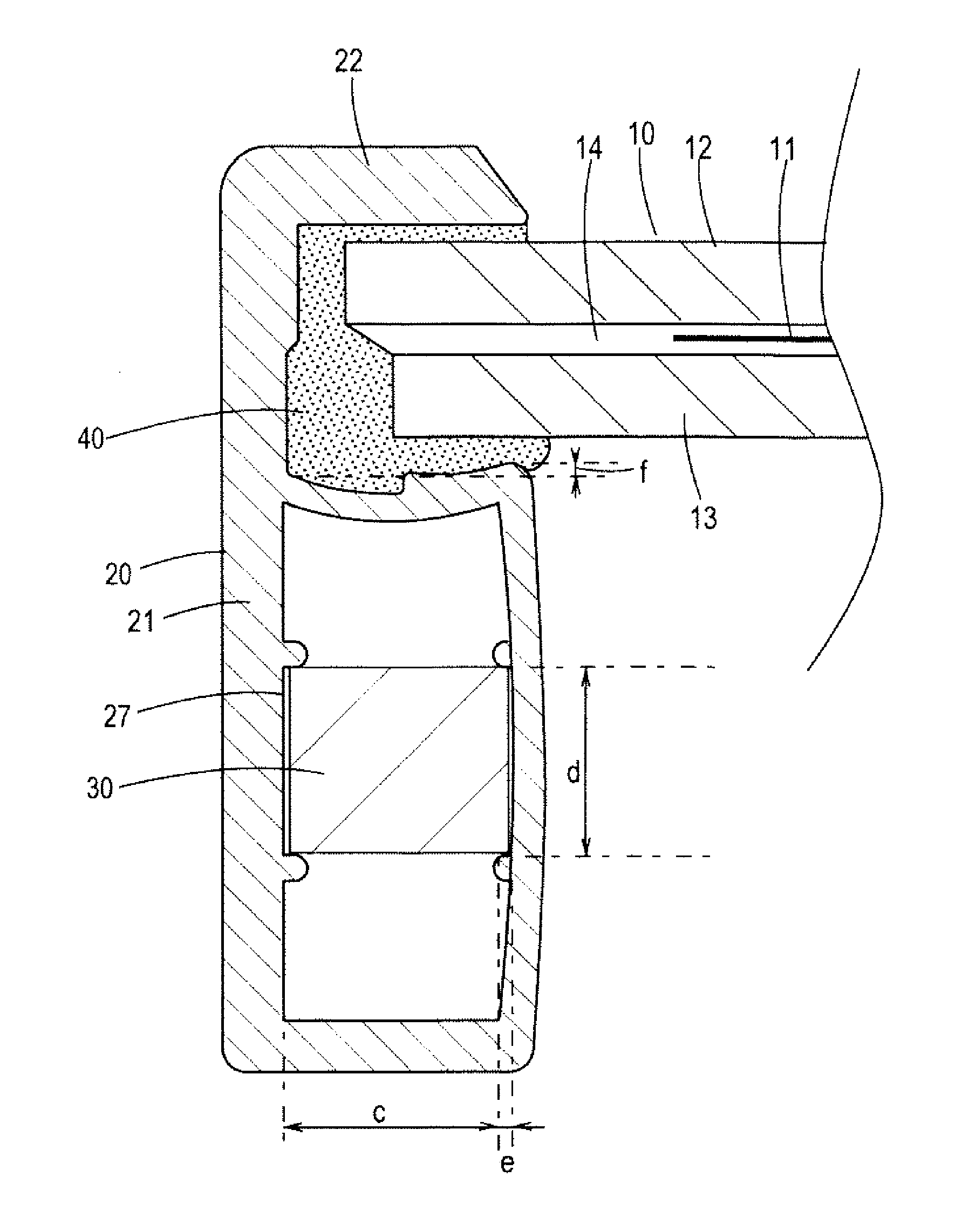
[0039]FIG. 5 is a schematic sectional view showing a photovoltaic module according to the invention. Referring to this figure, description is made on a general structure of this photovoltaic module.

[0040]The photovoltaic module of the invention includes a plurality of solar cells 11. The solar cell 11 comprises, for example, a crystalline semiconductor composed of monocrystalline silicon or polycrystalline silicon having a thickness on the order of 0.15 mm and is generally shaped like a square 100 mm on a side. However, the invention is not limited to this and may employ other solar cells.

[0041]Within the solar cell 11, an n-type region and a p-type region are formed, for example, while an interfacial area between the n-type region and the p-type region defines a junction for forming an electric field for carrier separation. An employed solar cell, for example, includes an intrinsic amorphous silicon layer interposed between a monocrystalline silicon substrate and an amorphous silic...

second embodiment

[0057]FIG. 8 and FIG. 9 are plan views showing the invention.

[0058]The second embodiment is arranged such that joint surfaces on which frames 20c, 20c abut on each other define a chamfered corner. For this purpose, the frames 20c, 20c in abutting contact include arc-shaped ends 25. Just as in the above embodiment, the frame 20c has a great outside wall thickness and a small inside wall thickness in section.

[0059]According to the frame 20c of the invention, the press-insertion of the corner piece 30 does not cause the deformation of an outside portion of the frame. Therefore, the corner formed by the frames 20c, 20c in abutting contact has a chamfered configuration because the frames 20c in abutting contact have their ends shaped like an arc.

[0060]In this manner, the chamfered corner is formed so that a person touching the corner with his / her hand or the like may not have pain or painful sensation such as caused upon contact against a sharply-angled article. Hence, the module may be ...


PUM


Abstract

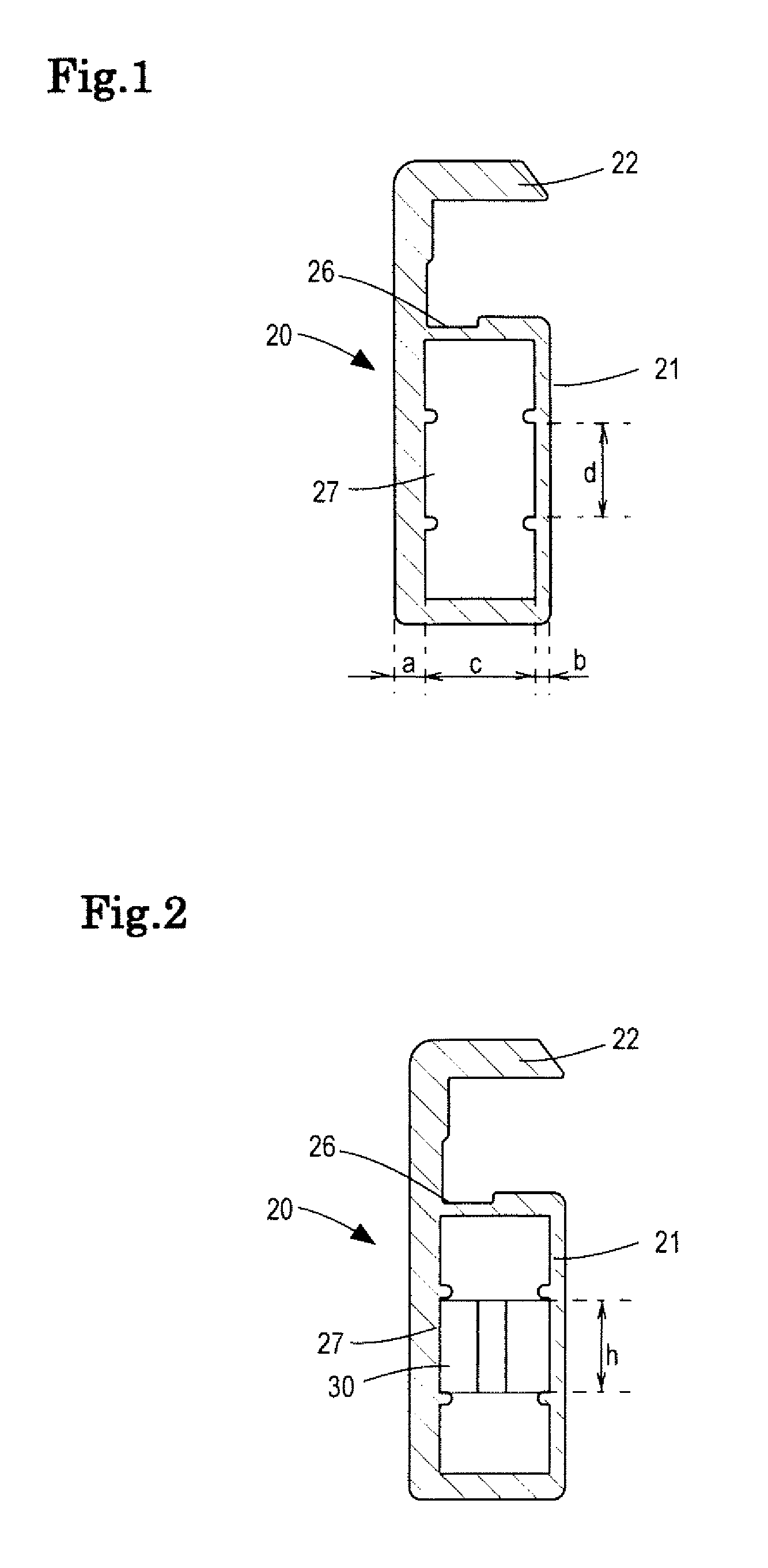
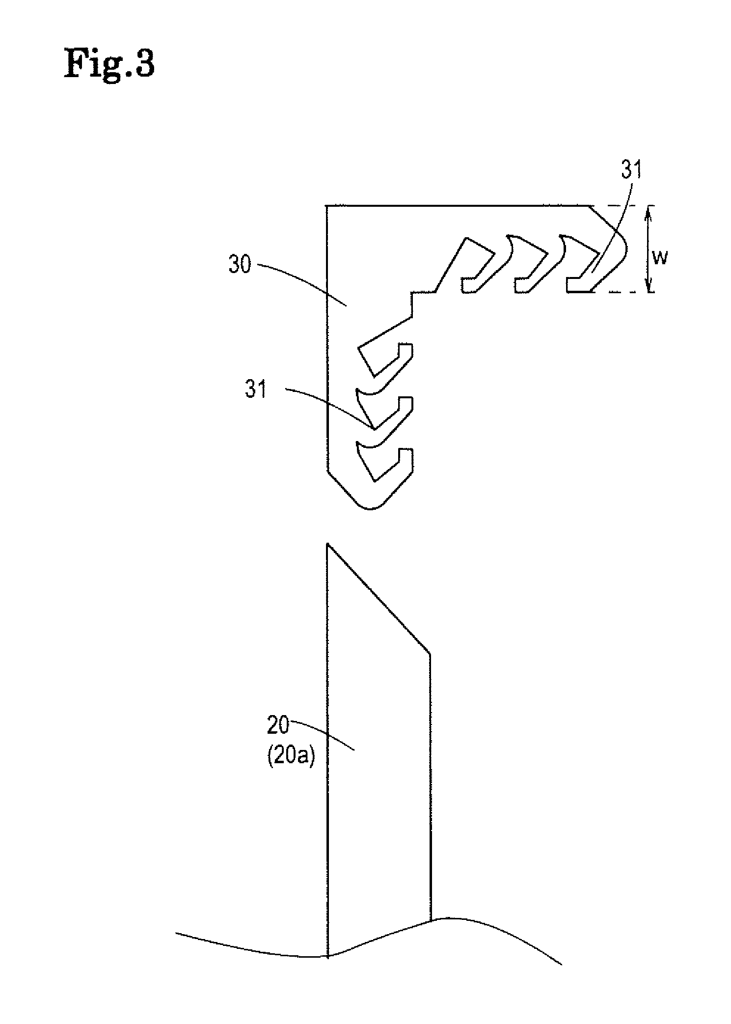
A photovoltaic module includes a photovoltaic module body and frames mounted to a periphery thereof. The frame includes a main body having a hollow structure and a fit-engagement portion located above the main body and fittingly receiving the periphery of the photovoltaic module body. The main body of the frame is formed with a mounting portion into which a press-insertion member is press-inserted and which has a great outside wall thickness and a small inside wall thickness in section. The frames are fixed to each other by press-inserting the press-insertion member into the mounting portions thereof.

Description

[0001]The priority application Number JP2009-39536 upon which this patent application is based is hereby incorporated by reference.BACKGROUND OF THE INVENTION[0002]1. Field of the Invention[0003]The present invention relates to a photovoltaic module wherein frames are mounted to a periphery of a photovoltaic module body including a plurality of solar cells.[0004]2. Description of the Prior Art[0005]Solar cells are expected to serve as a novel energy source because they can convert light energy from the sun directly into electric energy, the sun providing an inexhaustible supply of clean energy.[0006]Each solar cell provides a small output of several watts. Therefore, a common practice to use such solar cells as a source of electric power for household use or for use in building or the like is to connect a plurality of solar cells in series or in parallel thereby forming a photovoltaic module the output of which is increased to hundreds of watts. Such a photovoltaic module is disclos...

Claims


Application Information

Patent Timeline
Patent Type & Authority Patents(United States)
IPC IPC(8): B25G3/00H02N6/00B05C17/04A47G5/00H01L31/00
CPCF24J2/5211H02S20/00Y02E10/47Y10T403/4602Y02E10/50F24S25/20H02S30/10Y02B10/20H01L31/042
Inventor FURUKAWA, ISAO
Owner SANYO ELECTRIC CO LTD
Learn More