
Pressure engine, in particular, an internal combustion engine, with an annular structure

a technology of pressure engine and annular structure, which is applied in the direction of engines without rotary main shafts, engines with rotating cylinders, engines with sliding valves, etc., can solve the problems of high running noise level and additional efficiency loss, and achieve the effect of avoiding damage due to lack of flow medium and easy expansion

Active Publication Date: 2012-12-11
TRADLER ALOIS
View PDF29 Cites 2 Cited by
  • Summary
  • Abstract
  • Description
  • Claims
  • Application Information

AI Technical Summary

Benefits of technology

[0003]The object of the invention is to provide a pressure engine, in particular an internal combustion engine, which runs in a wear-resistant, low-noise and substantially true manner and for which a high efficiency is also tried to be achieved. The engine according to the invention is characterized in that the rotating piston comprises a piston housing; and, within the piston housing, an internal piston pressed towards the pressure chamber, in particular the combustion chamber, by a pre-stressing force, which also supports oneself on the piston housing, the internal piston being linearly displaceable against the pre-stressing force in relation to the piston housing in a longitudinal direction of the piston, the line of displacement of the internal piston tangentially passing the axis of the driven shaft at a distance. In this case, the pressure or combustion chamber is delimited by the annular housing and the rotating piston and does not require any cut-off members which are continuously moved into and out of the annular housing. The annular housing is substantially comprised of an annular groove being open towards the inside of the ring, which is formed for the purpose that therein the rotating piston may slide while the pressure or combustion chamber which also rotates is closely sealed. Therefore, a low-noise, true and smooth run is obtained, which can be implemented for low space requirements and for a high efficiency. The operation characteristics of the engine can be optimized by selecting the area ratio between piston and annular housing in the pressure or combustion chamber and the distance between the piston-displacement line and the axis of the driven shaft.
[0005]A particularly low-loss and low-wear run of the internal combustion engine is obtained if the internal piston travels in the piston housing, in its portion adjacent to the combustion chamber, on the inner wall of the piston housing in a non-contact manner with a narrow gap of 0.1 mm, for example, and is guided only by guide bushes having sealing rings on which the internal piston, namely the piston elements or the piston rod, acts in a sliding manner. Therefore, there are no oil scraper rings on the piston adjacent to the combustion chamber and the pressure loss caused by the existing gap is practically negligible. In addition, the internal piston may be designed in such a way that windows for the flow-through of cooling air are provided in the piston housing in the area between the first piston element in its first position and the second piston element in its outermost position and that the piston rod carries cooling fins in this area. Cooling of the, or each, rotating piston may limit thermal expansion and may therefore allow the above gap to be designed very narrow.
[0007]An improved afterburning of possible residual gases leaving the combustion chamber unburned is effected by branching off, from a compressed-air line connected to the window for supplying the combustion chamber with compressed air, or from an area of this window, a line leading in an afterburning chamber connecting, in relation to flow, to the connection for removing exhaust gases.

Problems solved by technology

The relevant mechanical system makes the engine complex, troublesome and susceptible to wear and results in an additional loss of efficiency and a high running noise level.

Method used


Image

  • Pressure engine, in particular, an internal combustion engine, with an annular structure
  • Pressure engine, in particular, an internal combustion engine, with an annular structure
  • Pressure engine, in particular, an internal combustion engine, with an annular structure

Examples


Embodiment Construction

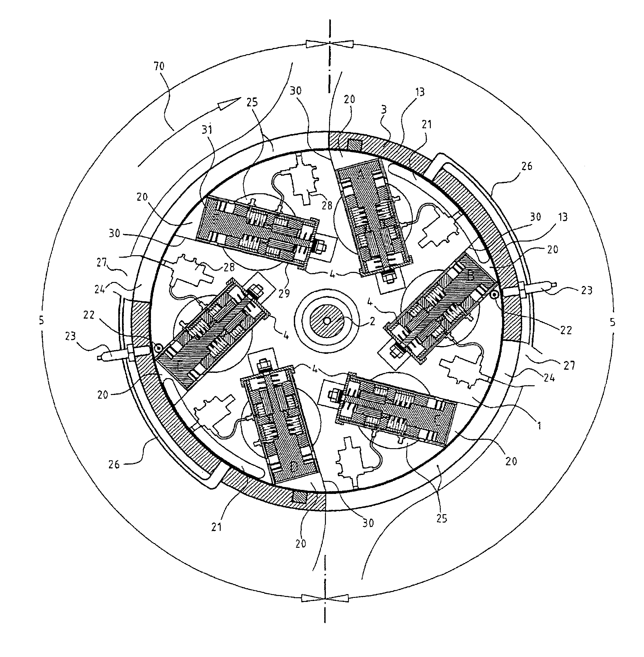
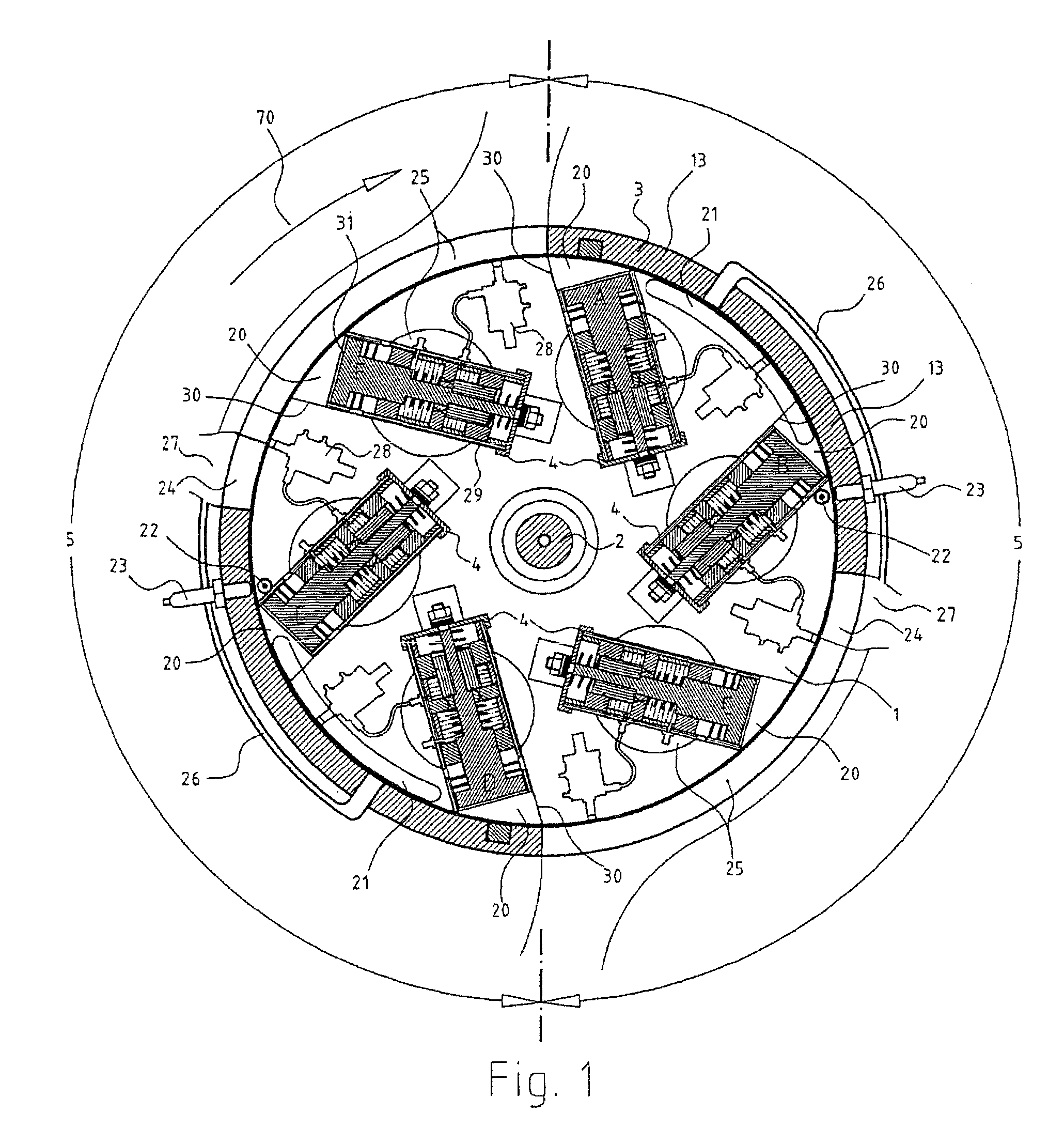
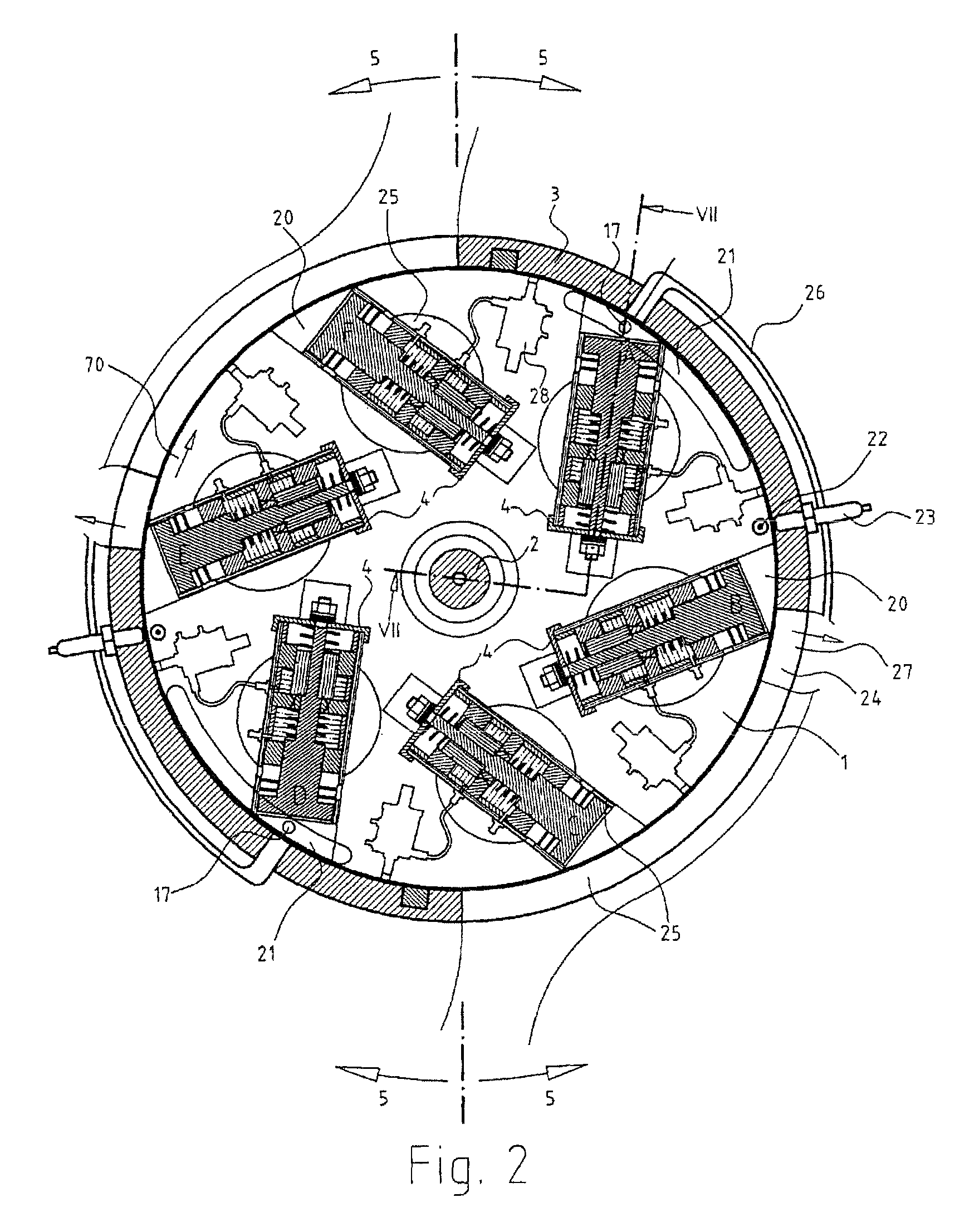
[0022]FIGS. 1 to 6 show the key components of a six-piston internal combustion engine according to the invention in different working cycles in a cross-sectional view. The engine components shown include a rotor 1 which is fixed, in a rotationally fixed manner, to an engine's driven shaft 2 determining the rotation axis of the rotor; and a stator 3 which is stationary or is fixed to the housing. In the example of FIG. 1, the rotor 1 includes six rotating pistons 4 which are denoted by A to F one after the other. The stator 3 has a disc or annular structure and its groove-like or tape-ring-like external surface approximately corresponds to the “cylinder” of a reciprocating internal combustion engine. In the example shown, the stator includes two working cycle lengths 5 having a repeating structure along the inner circumference of the stator 3. The number of the working cycle lengths can be compared to the number of poles of electric motors. A larger number of working cycle lengths 5 ...


PUM


Abstract

The invention relates to a novel pressure engine, in particular an internal combustion engine which includes an annular structure, a driven shaft running along the annular axis, an annular housing with a housing wall and at least one rotating piston that rotates in the annular housing along a circuit in a sealed manner in relation to the housing. The piston is rotationally fixed to the driven shaft by a connection member and delimits a segment shaped combustion chamber that rotates with the piston, at least on the side lying in the rotation direction when viewed from the combustion chamber. The chamber has connections at given points on the annular housing to a compressed air supply and to an exhaust system. This piston has a piston housing which contains an inner piston which is pushed towards the combustion chamber by a pre-tensioning force.

Description

FIELD OF THE INVENTION[0001]The invention relates to a pressure engine or pressure operated (power) engine with an annular structure, which comprises a driven shaft extending along the annular axis; an annular housing including a housing wall and at least one rotating piston rotating within the annular housing along a circular path in a sealed manner against the housing, the rotating piston being connected to the driven shaft through a connecting link in a rotationally fixed manner and delimiting within the annular housing a co-rotating, e.g. ring-segment-like pressure chamber at least on the side located in the direction of rotation as seen from the pressure chamber; connections, which are formed in predetermined positions of the annular housing, to a compressed-air supply, to a fuel supply in case of an internal combustion engine, and to an exhaust system. The invention relates in particular to an internal combustion engine. It is, however, well-known that internal combustion engi...

Claims


Application Information

Patent Timeline
Patent Type & Authority Patents(United States)
IPC IPC(8): F02B53/00F02B75/26F02B53/04F02B53/10F01B3/00F01B3/04F16J1/24F01L5/10
CPCF01B13/045F02B57/00F01B11/007F01B11/02
Inventor TRADLER, ALOIS
Owner TRADLER ALOIS
Learn More