
Mobile wellsite monitoring

a mobile, well-site technology, applied in the direction of simultaneous indication of multiple variables, special data processing applications, wireless architecture usage, etc., can solve the problems of difficult to collect data, information and status updates, and difficult to supply equipment, tools and manpower to such wellsites, so as to prevent or minimize costly mistakes and increase the level of safety

Active Publication Date: 2012-12-04
OCCIDENTAL PERMIAN LTD
View PDF47 Cites 19 Cited by
  • Summary
  • Abstract
  • Description
  • Claims
  • Application Information

AI Technical Summary

Benefits of technology

"The patent describes a method for monitoring a wellsite using a mobile monitoring platform. The platform includes a chassis with wheels and a mast that can extend vertically upward from the chassis. It also includes a transceiver with a wireless modem and an antenna. The platform receives wellsite data from sensors at the wellsite and wirelessly transmits the data to a remote monitoring station in real-time. The method allows for real-time monitoring of wellsite data, including wellsite images, environmental data, and operation data. The platform can also be powered by solar energy and can be transported between different wellsites. The technical effects of the patent include improved monitoring of wellsites and increased efficiency in wellsite operations."

Problems solved by technology

Often, it may be difficult to supply equipment, tools, and man power to such wellsites as well as remove the equipment and tools once.
Even more difficult may be the gathering of data, information, and status updates from wellsites because of their remote locations.
Moreover, up-to-date or real-time information is often unavailable from a wellsite due to its remote location.
Such historical data may be difficult to obtain, however, due to the remote location of each wellsite.
Thus, the system may greatly decrease costs associated with poor business decisions, reduced safety incidents, wellsite operation downtime, theft, vandalism, and even inclement weather at a wellsite.

Method used


Image

  • Mobile wellsite monitoring
  • Mobile wellsite monitoring
  • Mobile wellsite monitoring

Examples


Embodiment Construction

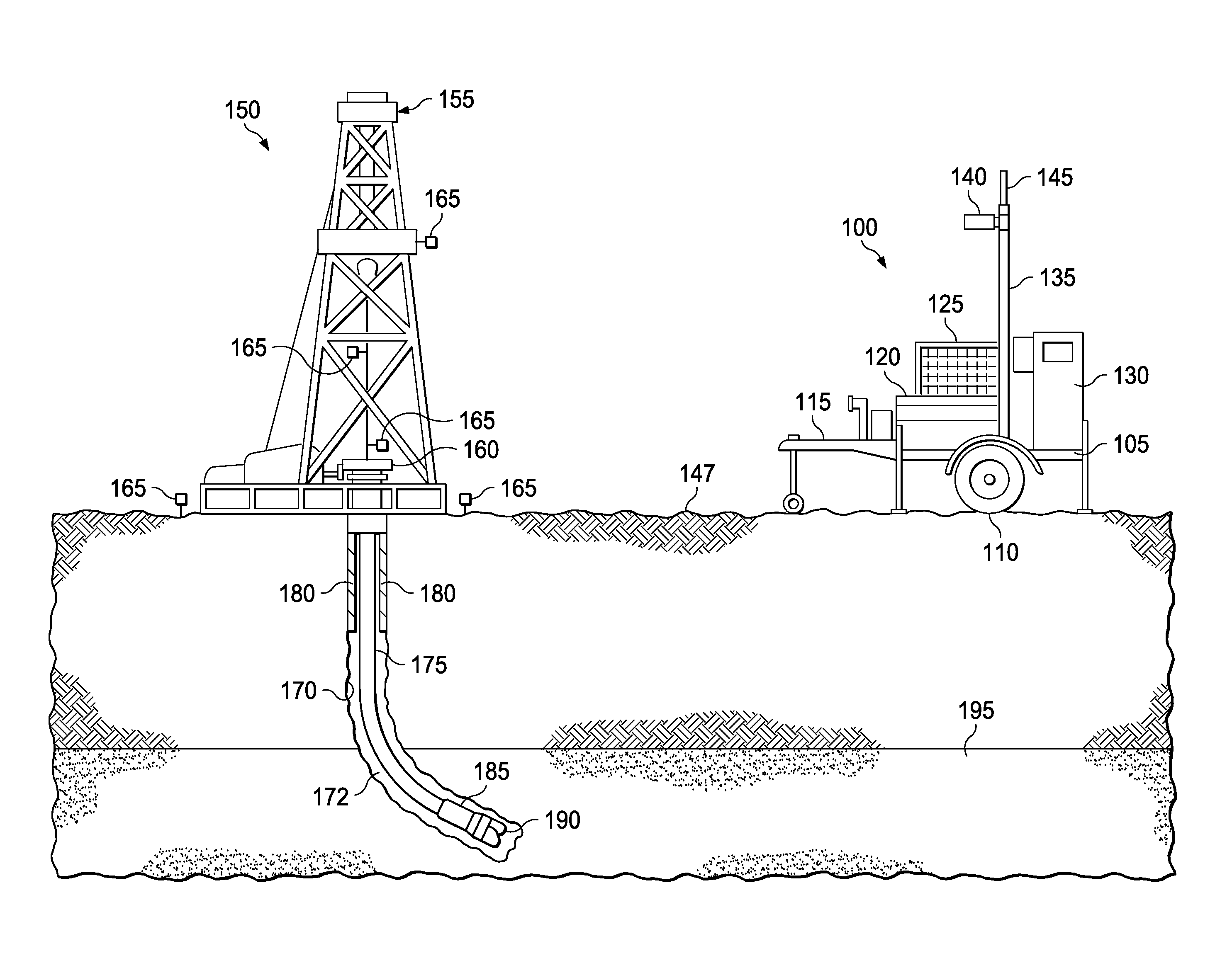
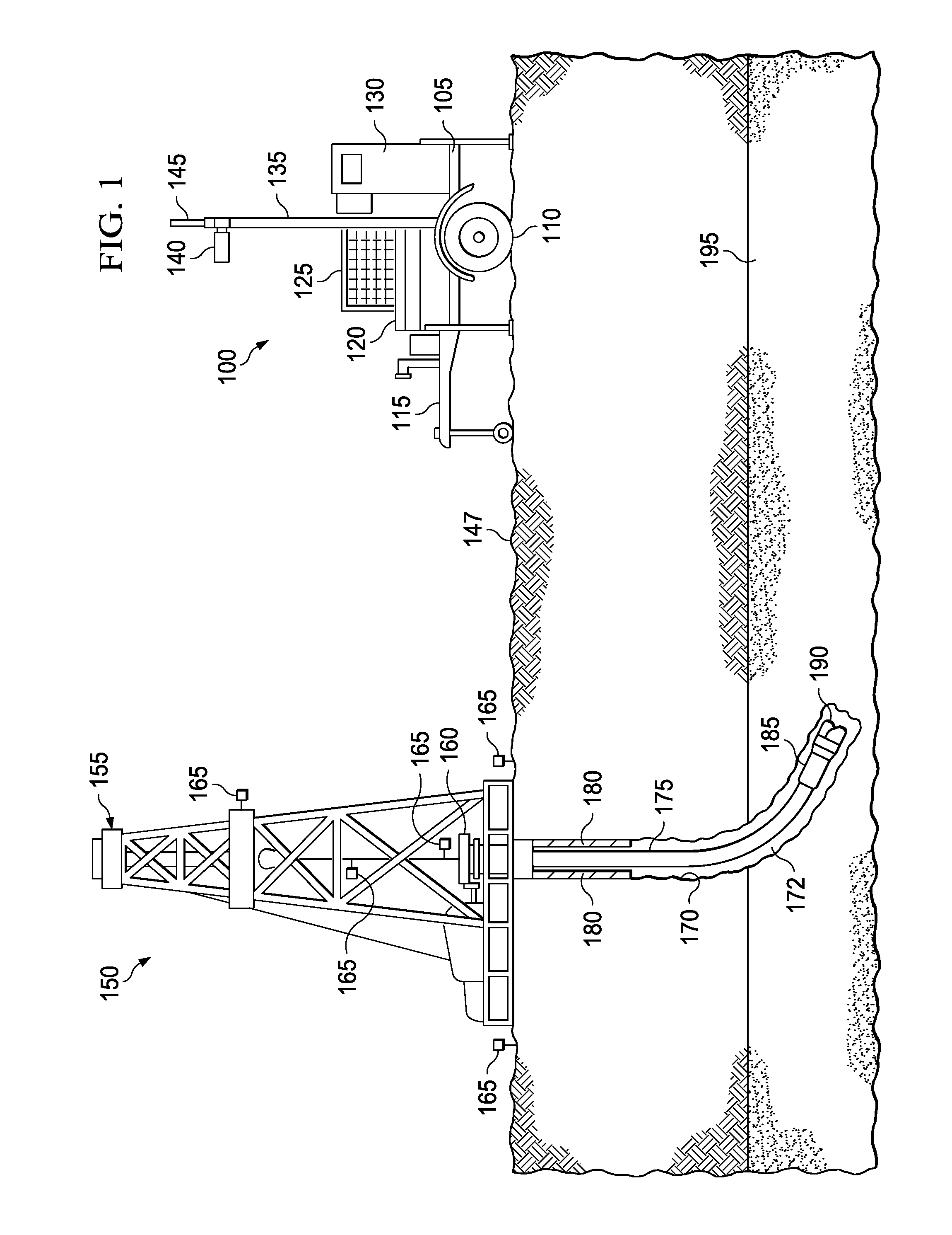
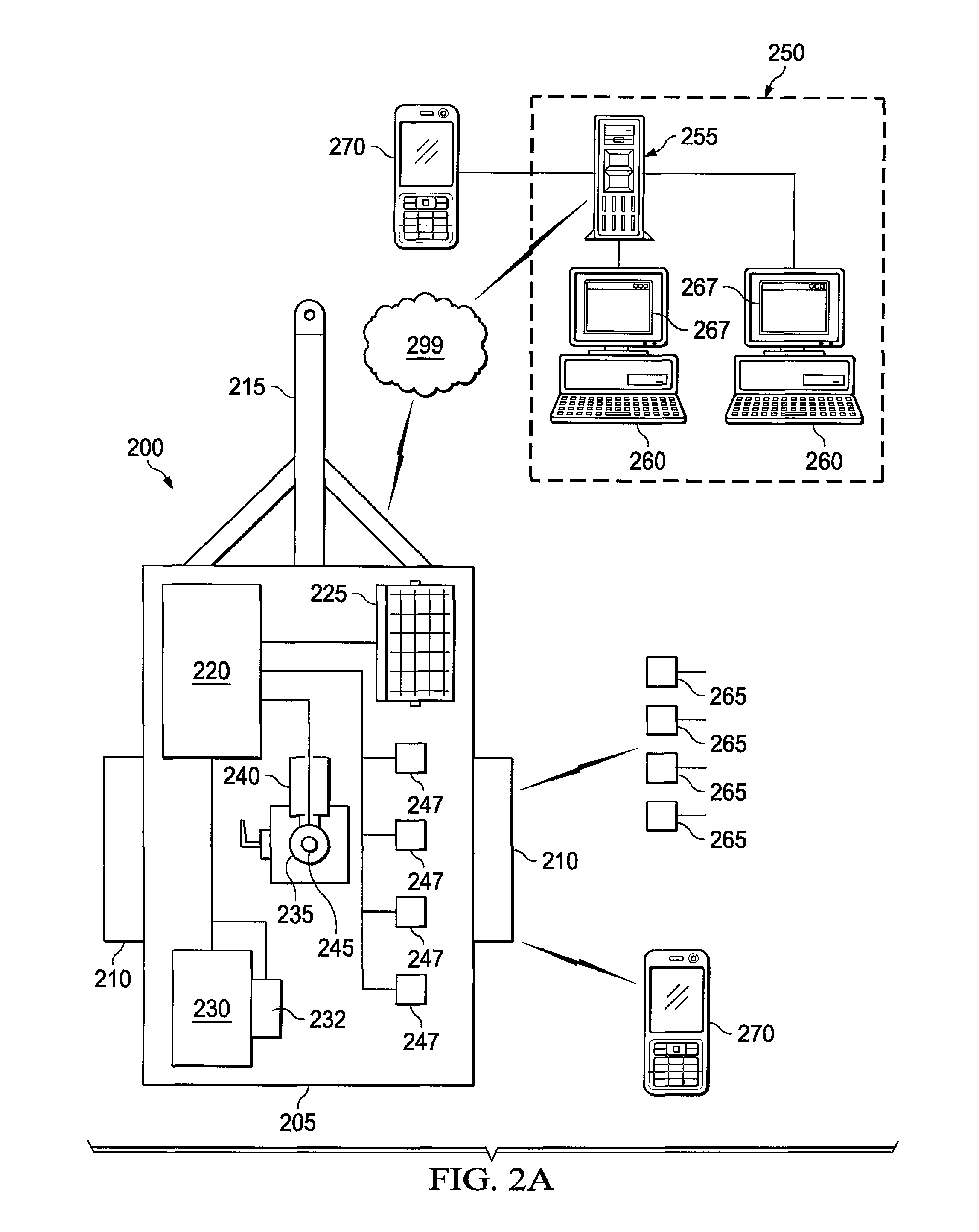
[0049]One implementation of a mobile wellsite monitor according to the present disclosure may allow for one or more wellsite variables to be monitored and / or measured by wireless communication between one or more sensors monitoring such data at the wellsite and the mobile wellsite monitor. The mobile wellsite monitor may receive such wireless data and store all or a portion of such data while also wirelessly transmitting all or a portion of such data to a remote monitoring station. The mobile wellsite monitor, according to some embodiments of the present disclosure, may also capture one or more wellsite images, as well as receive wellsite job event data (e.g., start and stop times of certain wellsite job events) from one or more wellsite companies, such as a well operator, directional drilling company, and / or a well completion company. Such job event data may also be wirelessly communicated to the remote monitoring station. In some embodiments, the wellsite variable data and / or job ...


PUM


Abstract

Methods for monitoring a wellsite include transporting a mobile monitoring platform to a wellsite. The mobile monitoring platform includes a transportable chassis including two or more wheels; a mast supported by the platform and extendable vertically upward from the chassis; a transceiver including a wireless modem and an antenna; a controller adapted to communicate with the transceiver; and a power module electrically coupled to at least one of the transceiver and the processor. The methods include wirelessly receiving, at the transceiver, wellsite data from a plurality of sensors at or adjacent the wellsite; and wirelessly transmitting, in real-time, the wellsite data to a remote monitoring station.

Description

CLAIM OF PRIORITY[0001]This application claims priority under 35 U.S.C. §119(e) to U.S. Provisional Patent Application Ser. No. 61 / 141,507, filed on Dec. 30, 2008, the entire contents of which are hereby incorporated by reference.TECHNICAL BACKGROUND[0002]This disclosure relates to wellsite monitoring and, more particularly, to wellsite monitoring utilizing a mobile monitoring platform communicatively coupled to a remote monitoring station and accessible via a communication network, such as the Internet.BACKGROUND[0003]A wellsite, which often includes a well service rig, drilling equipment, logging equipment, and other completion equipment, is often located far from population centers and in remote rural areas. Often, it may be difficult to supply equipment, tools, and man power to such wellsites as well as remove the equipment and tools once. Even more difficult may be the gathering of data, information, and status updates from wellsites because of their remote locations. For examp...

Claims


Application Information

Patent Timeline
Patent Type & Authority Patents(United States)
IPC IPC(8): G06F11/30G01M99/00G06F17/40G06F19/00E21B47/12G16Z99/00
CPCE21B47/12G06Q10/06393H04Q9/00H04N7/185H04Q2209/40G08C17/02G06F17/40G16Z99/00G06F11/30G01M99/00
Inventor HOBBS, KIRKROWE, TERRELLSISSON, JUDY
Owner OCCIDENTAL PERMIAN LTD
Learn More