Furniture drive with a drive unit

a technology of drive unit and drive unit, which is applied in the direction of dynamo-electric machines, door/window fittings, applications, etc., can solve the problem that the electric motor used cannot provide full torque, and achieve the effect of low torque and full torqu

Inactive Publication Date: 2012-12-04
JULIUS BLUM GMBH
View PDF19 Cites 5 Cited by
  • Summary
  • Abstract
  • Description
  • Claims
  • Application Information

AI Technical Summary

Benefits of technology

[0005]That object is attained by a furniture drive having the features of the present invention. By virtue of a variable radial spacing in the direction of rotation of the surface of the roller, on to which a flexible force transmission means is applied or wound, a control cam is provided for the force transmission means. By virtue of that control cam, it is possible to targetedly control the necessary torque that the furniture drive must apply by way of the force transmission means for moving the furniture part. If, for example, the radial spacing of the surface and thus the radial spacing of the control cam is slight, the torque to be applied is also low. In that way, the electric motor can more rapidly provide its optimum rotary speed and thus its full torque.
[0006]In a particularly preferred embodiment of the invention, the roller itself is driven by the electric motor. Due to the above-specified measure, a lower torque is initially necessary to move the furniture part, whereby generally the motor power or the size of the motor of the furniture drive can be reduced.
[0007]It is particularly advantageous for the control cam to be designed in such a way that, at the beginning of the movement, the radial spacing of the control cam relative to the axis of rotation is kept at a minimum and then slowly increases until it reaches a maximum radial spacing. That measure means that the motor can more quickly reach its optimum rotary speed. In addition, it may be advantageous that, in the further configuration of the control cam, by way of which the force transmission means is caused to bear against or is wound on to a surface, the radial spacing relative to the axis of rotation of the roller is kept constant. It can be provided in that respect that the winding length corresponds to the length of the force transmission means, for example a cable or belt.
[0010]A particularly preferred embodiment of the invention provides that the radial spacing of the control cam in a first region increases from a minimum value to a maximum value and remains constant in a second region following the first region. That complies with the construction of a furniture drive according to the invention, especially as torque control is necessary only at the beginning of a change in motion (that is to say, for starting and decelerating the furniture part), while for the major part of the movement the constant torque that is prevailing after the attainment of a certain rotary speed of the electric motor is fully sufficient. In addition, such a control cam with a second region involving a constant radial spacing can avoid the roller which is rotatable about an axis becoming too large and no longer being suitable for installation in a furniture carcass.

Problems solved by technology

A disadvantage of furniture drives of the general kind set forth is that the electric motors used can only provide the full torque, as from a certain rotary speed.
That leads to problems when starting up and decelerating furniture parts, for example drawers, by means of a furniture drive of the general kind set forth.
In addition, such a control cam with a second region involving a constant radial spacing can avoid the roller which is rotatable about an axis becoming too large and no longer being suitable for installation in a furniture carcass.

Method used


Image

  • Furniture drive with a drive unit
  • Furniture drive with a drive unit
  • Furniture drive with a drive unit

Examples


Embodiment Construction

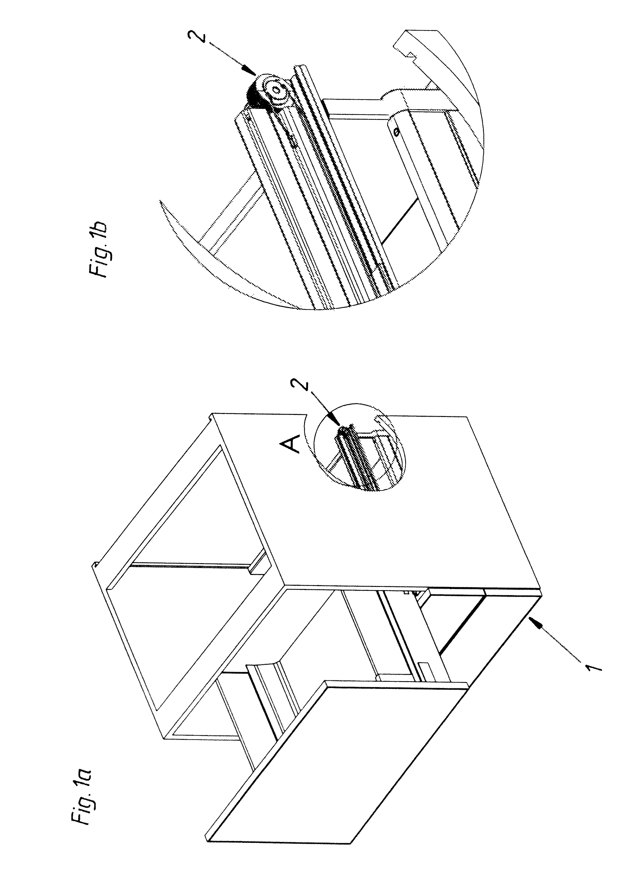
[0023]It will be presupposed that both opening and closing of the movable furniture part (for example flap of an article of furniture or a drawer) is possible with a furniture drive according to the invention. In the illustrated embodiment, that is achieved by a reversible electric motor. FIG. 1a shows an embodiment of a furniture carcass 1 according to the invention. In this case, a drawer is moved open and shut by a furniture drive 2 according to the invention. FIG. 1b shows a detail view on an enlarged scale of the portion marked by A, illustrating the furniture drive 2 according to the invention.

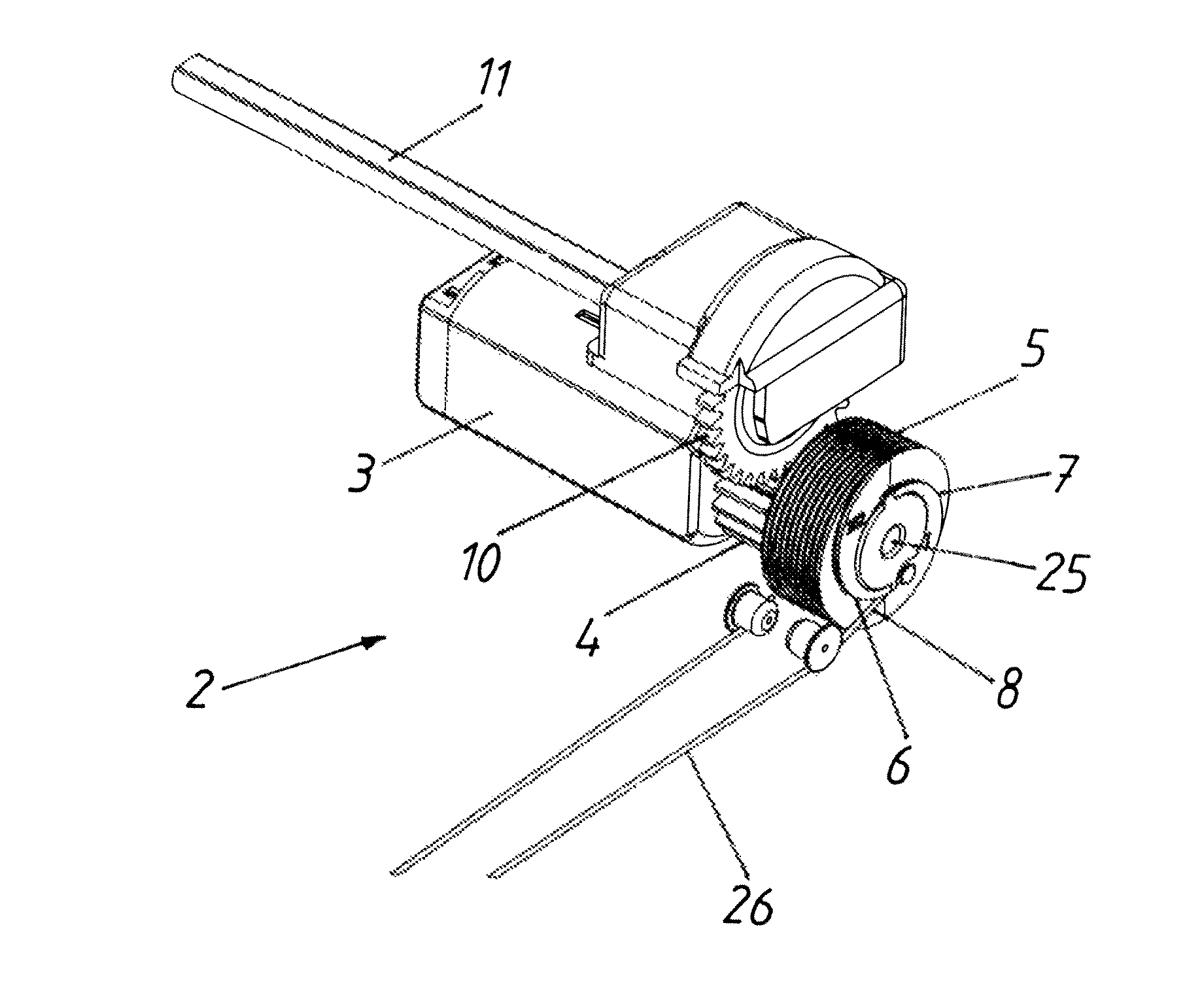
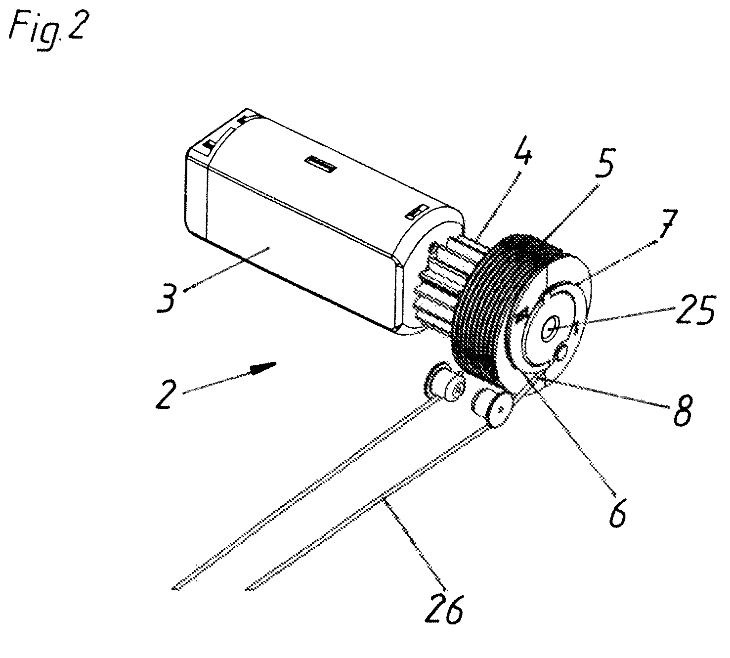
[0024]FIG. 2 shows a view of an embodiment of a furniture drive according to the invention. In this case, a roller 5 is driven by an electric motor 3 by way of a drive shaft (not shown) on which a gear 4 is carried. The roller 5 has a surface on which a force transmission member (which in this embodiment is provided by a cable line 26 having a first cable end 8) is wound or applied. The ...


PUM


Abstract

A furniture drive has a drive unit including an electric motor and a roller that is rotatable about an axis, the roller having a surface for attaching or winding up a flexible force transmission member. The radial distance of the surface changes in the rotational direction of the roller for forming at least one control cam for the force transmission member.

Description

[0001]This application is a Continuation of International application PCT / AT2009 / 000065, filed Feb. 19, 2009, the entire disclosure of which is incorporated herein by reference.BACKGROUND OF THE INVENTION[0002]The present invention concerns a furniture drive comprising a drive unit which has an electric motor and a roller which is rotatable about an axis, wherein the roller has a surface for applying or winding up a flexible force transmission means.[0003]Furniture drives with electric motors are already part of the state of the art. Thus, for example, WO 2007 / 147180 discloses a pull-in device for a drawer, wherein an electric motor rotates a roller by way of a drive unit and in so doing winds a pulling means on to the roller, whereby the drawer connected to the pulling means is pulled in the closing direction. A disadvantage of furniture drives of the general kind set forth is that the electric motors used can only provide the full torque, as from a certain rotary speed. That leads...

Claims


Application Information

Patent Timeline
IPC IPC(8): A47B88/04A47B95/00
CPCA47B88/0414E05F15/643E05Y2900/20A47B88/457A47B88/447
Inventor GASSER, INGO
Owner JULIUS BLUM GMBH
Why Eureka
Try Eureka