
Frame rate conversion apparatus and method

a frame rate conversion and apparatus technology, applied in the field of system and a method for frame rate conversion, can solve the problems of generating erroneous images, unnatural interpolation images with a strangeness, and the tendency for erroneous interpolation to occur, so as to reduce the feeling of strangeness and reduce the generation of erroneous images

Active Publication Date: 2012-11-27
JVC KENWOOD CORP
View PDF24 Cites 2 Cited by
  • Summary
  • Abstract
  • Description
  • Claims
  • Application Information

AI Technical Summary

Benefits of technology

[0016]According to the present invention, there is a system as well as a method for frame rate conversion adapted to reduce erroneous interpolation due to erroneous detection of motion vector, allowing for a conversion of frame rate to obtain natural images with a reduced feeling of strangeness.

Problems solved by technology

In frame rate conversion apparatuses of motion compensating type, there is generation of inherently non-existent images predicted from temporarily antecedent and subsequent images, with potential generation of erroneous images, that is, an occurrence of so-called erroneous interpolation.
For instance, there may be differences of motion between a spatially anterior foreground and a spatially posterior background, with tendencies for erroneous interpolation to occur.
Between foreground and background, there is a boundary about which erroneous detection of motion vector tends to occur, resulting in erroneous interpolation causing unnatural interpolation images with a feeling of strangeness, as an issue.

Method used


Image

  • Frame rate conversion apparatus and method
  • Frame rate conversion apparatus and method
  • Frame rate conversion apparatus and method

Examples


Embodiment Construction

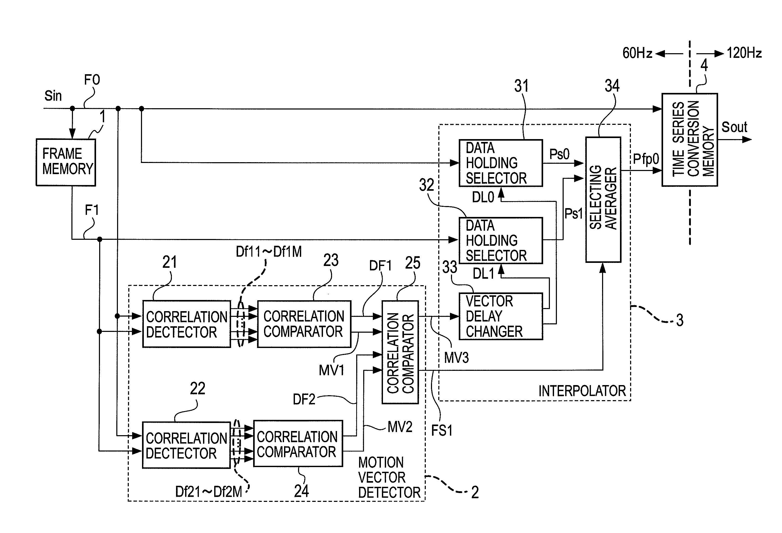
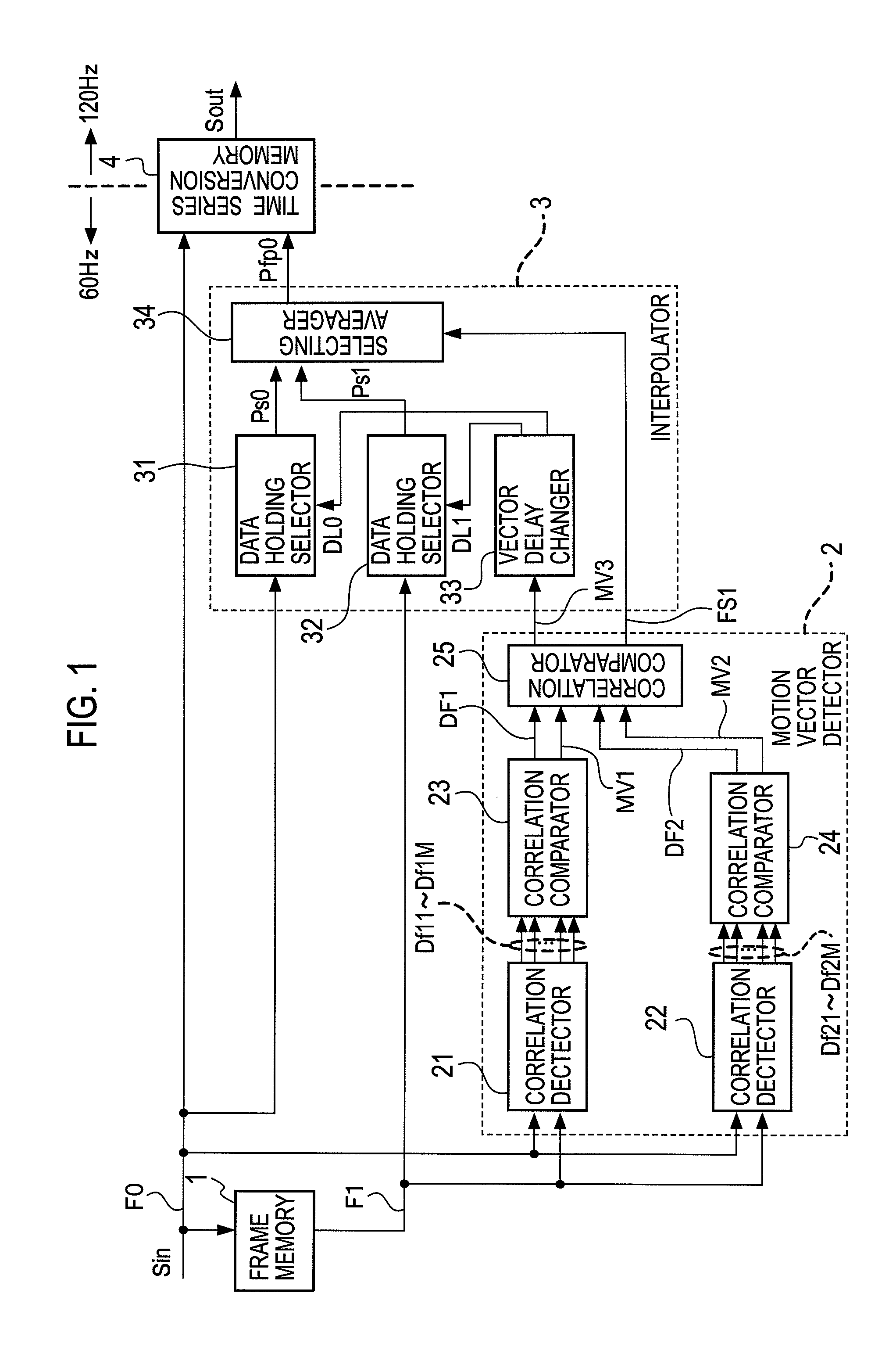
[0027]There will be described a system and a method for frame rate conversion according to an embodiment of the present invention, with reference to the accompanying drawings. In FIG. 1, given a picture signal Sin with a frame frequency of 60 Hz, it has a sequence of pixel data each respectively input to a frame memory 1, a motion vector detector 2, an interpolator 3, and a time series conversion memory 4. The frame memory 1 has input pixel data delayed by 1 frame to output. Letting F0 be a current frame of picture signal Sin input thereto, and F1 be a frame output from the frame memory 1 as a 1-frame previous one to the current frame. The frame F1 has a sequence of pixel data input to the motion vector detector 2, and the interpolator 3.

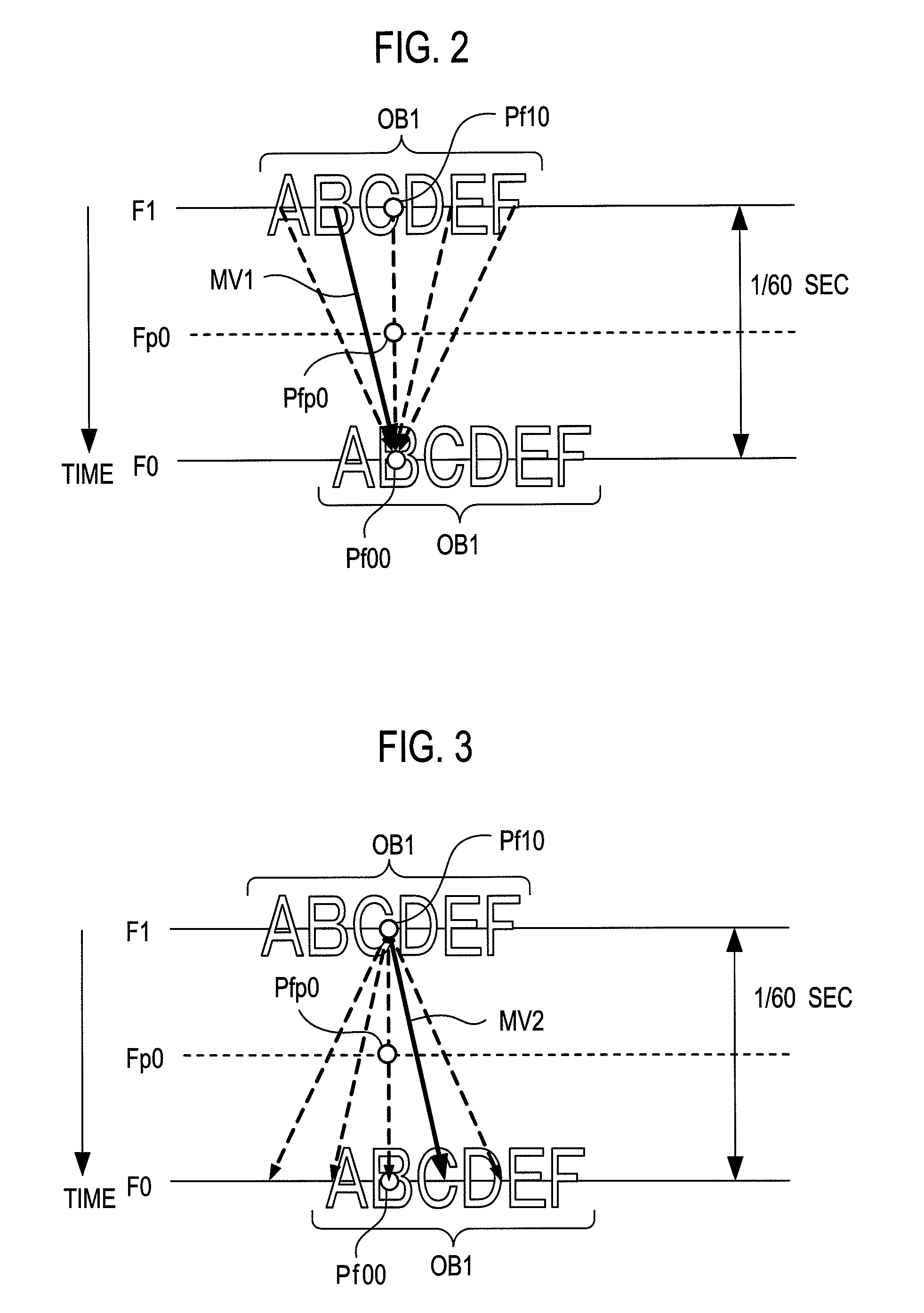
[0028]The motion vector detector 2 includes a combination of correlation detectors 21 and 22 and correlation comparators 23 to 25. One correlation detector 21 employs a first correlation detecting method illustrated in FIG. 2, to detect correlations...


PUM


Abstract

Correlation detectors 21 and 22 employ two different correlation detecting methods to determine correlations. Correlation comparators 23 and 24 output correlation values DF1 and DF2, and motion vectors MV1 and MV2 in directions representing largest correlation values. A correlation comparator 25 selects one of the motion vectors larger in correlation, as a motion vector MV3, to output an interpolation control signal FS1 to determine an interpolation method at an interpolator 3. The interpolator 3 is operative in accordance with the interpolation control signal FS1, to select any one out of two different one-side interpolations and a both-side interpolation, to generate interpolation pixel data fp0.

Description

[0001]This is a National Phase Application filed under 35 U.S.C. 371 as a national stage of PCT / JP2010 / 067674, filed on Oct. 7, 2010, an application claiming the benefit from Japanese Application No. P2009-234125 filed on Oct. 8, 2009, the entire content of each of which is hereby incorporated by reference in its entirety.TECHNICAL FIELD[0002]The present invention relates to a system and a method for frame rate conversion adapted for use of motion vectors of moving images to generate interpolation pixels, interpolate interpolation frames between real frames, and make a conversion of frame rate.BACKGROUND ART[0003]There are image display systems using liquid crystal panels to display moving images, with tendencies to produce afterimages. To this point, for reduction of afterimages, there is use of interpolation frames to be interpolated between real frames of picture signals, for increasing frames in number, converting e.g. a vertical frequency of 60 Hz in frame rate to a vertical fr...

Claims


Application Information

Patent Timeline
Patent Type & Authority Patents(United States)
IPC IPC(8): H04N7/01
CPCG06T3/4007H04N7/0132H04N7/014H04N19/587H04N19/176H04N19/172H04N19/132H04N19/139H04N7/01G06T7/20
Inventor NOGUCHI, HIROSHI
Owner JVC KENWOOD CORP
Learn More