Electric lamp
a technology of electric lamps and lamps, applied in the field of electric lamps, can solve the problems of affecting the omnidirectional light distribution, and large lamps, and achieve the effects of reducing the number of lamps, reducing the number of different lamp parts, and facilitating manufactur
- Summary
- Abstract
- Description
- Claims
- Application Information
AI Technical Summary
Benefits of technology
Problems solved by technology
Method used
Image
Examples
first embodiment
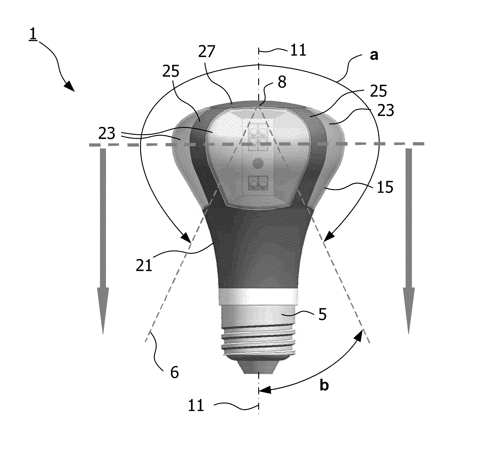
[0036]In FIG. 2A a side view of the lamp 1 according to the invention is shown. The lamp has a socket 5, a convenient E27 Edison fitting, in which the bulb 3 comprising cooling means 21 is mounted. The outer surface 15 of bulb 3 is formed both by light transmittable surface sub-areas 23, four arches 25 (of which only two are shown) and an adjoining top 27 of the cooling means, which feature is more clearly visible in the top view shown in FIG. 2B along axis 11. The cooling means extend from inside the bulb into the outer surface of the bulb and are formed as solid arches. In the embodiment of FIG. 2A, surfaces are mutually flush at locations at the outer surface of the bulb where said surfaces of both the cooling means and the light transmittable sub-areas border each other. The cooling means hamper only to a small extent the distribution of light as emitted by the light source (not shown) through the light transmittable surface 15, and to a significantly lesser degree than the prio...
second embodiment
[0037]In FIG. 2D a perspective view, partly broken away, of the lamp 1 according to the invention is shown, i.e. the light transmittable sub-areas are formed by releasably fixed light transmittable parts, of which two are left out, which light transmittable parts are provided with click / snap elements enabling easy assembly onto the lamp by interconnecting with clicking elements 32 provided on the cooling means 21. Some of the components inside the bulb 3 are visible, including the light source 7 which is made up of a plurality of LEDs 7a,7b mounted on a PCB 9, and cooling means 21 which extend from the PCBs inside the bulb into the outer surface 15 of the bulb. The PCBs are arranged around axis 11. The cooling means are shaped as recesses extending from the bulb outer surface towards the axis and are coated on a side 29 facing the LEDs with a reflective coating 31 to counteract light losses due to absorption of light by the cooling means and thus to increase the efficiency of the la...
third embodiment
[0038]FIG. 3A shows a side view of the lamp 1 according to the invention. The lamp has a socket 5, a convenient E27 Edison fitting, in which the bulb 3 comprising cooling means 21 is mounted. The outer surface 15 of the bulb is formed both by six light transmittable surface sub-areas 23 of the same shape, six corrugated arches 25 (of which only four are shown) and an adjoining top 27 of the cooling means. In the lamp of FIG. 3A the light transmittable sub-areas each are surrounded by respective cooling means. The cooling means are not flush with the light transmittable surface but are partly laid over said surface, such that the cooling means together with the light transmittable surface form an undulated bulb outer surface. The cooling means in this lamp do not extend from inside the bulb into and beyond the outer surface 15 of the bulb, but only form part of the bulb outer surface. FIG. 3B shows a vertical cross-section of the lamp 1 of FIG. 3A. As the lamp is a DC lamp, an electr...
PUM
 Abstract
Description
Claims
Application Information
 - R&D
- Intellectual Property
- Life Sciences
- Materials
- Tech Scout
- Unparalleled Data Quality
- Higher Quality Content
- 60% Fewer Hallucinations
Browse by: Latest US Patents, China's latest patents, Technical Efficacy Thesaurus, Application Domain, Technology Topic, Popular Technical Reports.
© 2025 PatSnap. All rights reserved.Legal|Privacy policy|Modern Slavery Act Transparency Statement|Sitemap|About US| Contact US: help@patsnap.com


