
Interlocking reverse hip prosthesis and method

a hip and interlocking technology, applied in the field of hip prosthesis, can solve the problems of becoming very difficult for the femoral cup to dislocate, and achieve the effects of reducing the number of wear particles released, improving weight distribution, and reducing the wear of the surfaces in conta

Active Publication Date: 2012-11-20
HIP INNOVATION TECHONOLOGY LLC
View PDF60 Cites 92 Cited by
  • Summary
  • Abstract
  • Description
  • Claims
  • Application Information

AI Technical Summary

Benefits of technology

The present invention is a new type of hip prosthesis that has a reversed arrangement of the articulating surfaces, namely the ball and socket. This new design has several technical benefits. Firstly, the femoral cup is securely attached to the femoral stem using a Morse taper, which ensures stability and reduces the risk of dislocation. Secondly, the femoral cup is designed to glide over the articulating acetabular ball, which improves weight distribution and reduces wear and tear of the surfaces in contact. Lastly, the articulating surfaces of the two components are fully in contact, which further reduces wear and tear. Overall, this new design offers improved outcomes and reduced complications in hip replacement surgery.

Problems solved by technology

Furthermore, by its very geometrical configuration, it becomes very difficult for the femoral cup to dislocate when the range of motion increases since it becomes constrained in the hemispherical locking space between the acetabular cup and the acetabular ball.

Method used


Image

  • Interlocking reverse hip prosthesis and method
  • Interlocking reverse hip prosthesis and method
  • Interlocking reverse hip prosthesis and method

Examples


Embodiment Construction

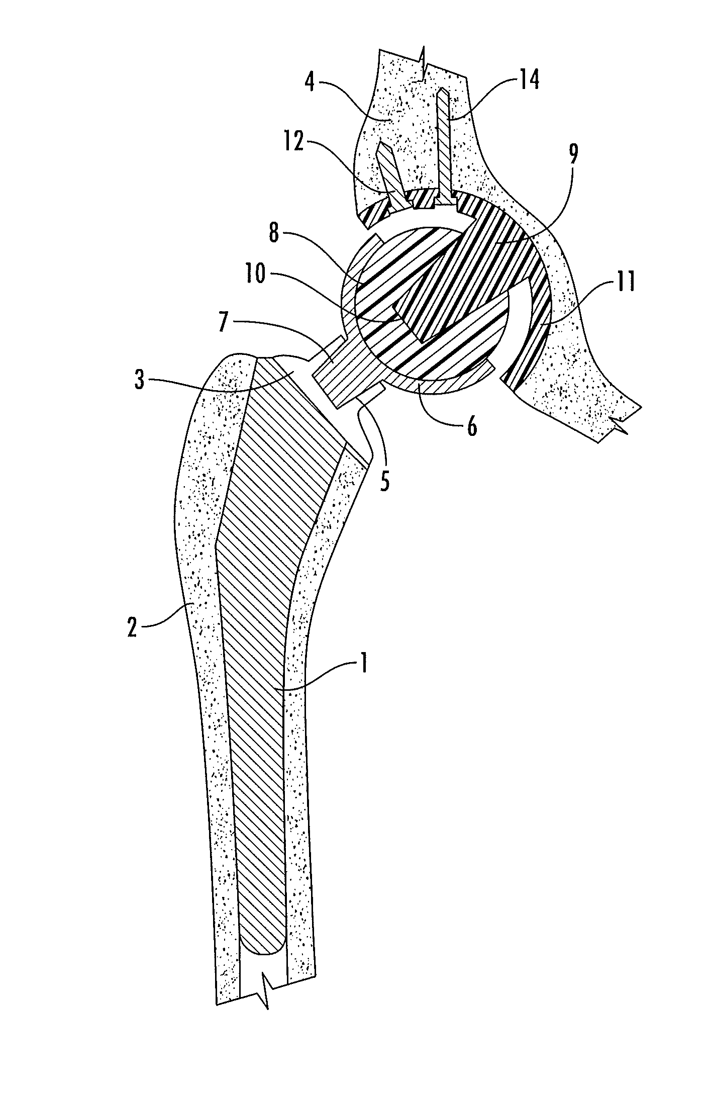
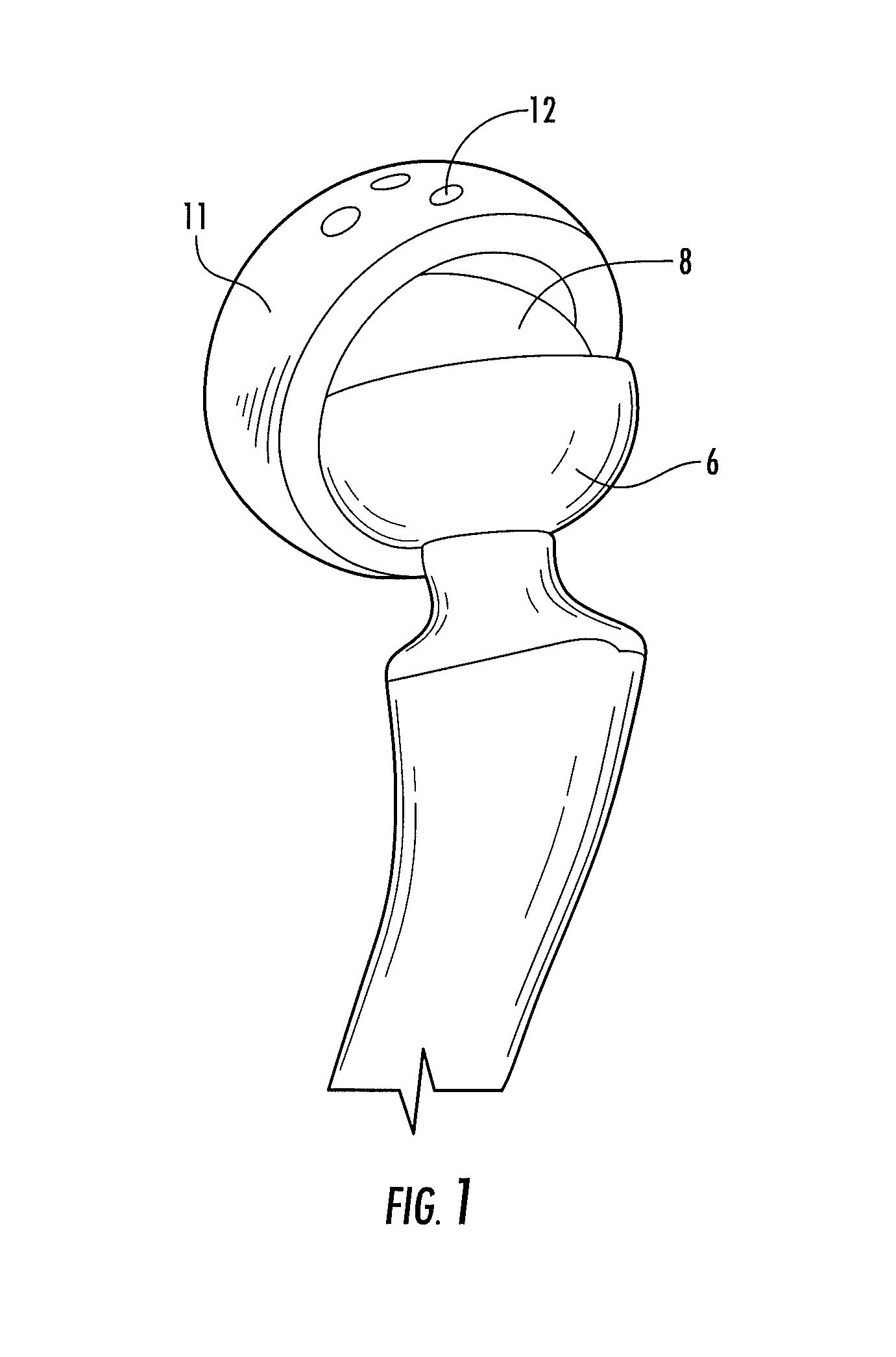
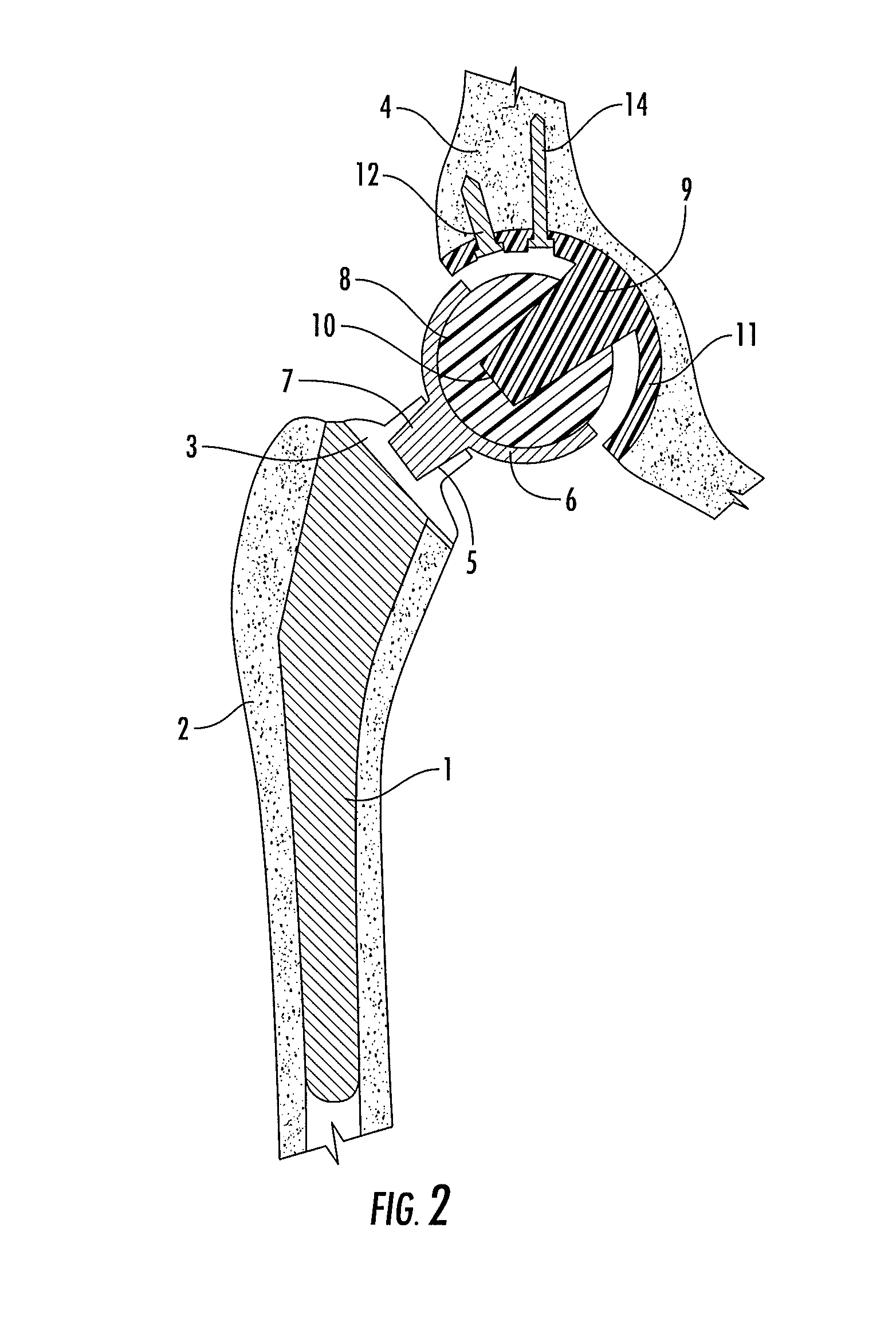
[0019]Turning now descriptively to the drawings, in which similar reference characters denote similar elements throughout the several views, the attached figures illustrate an interlocking reverse hip prosthesis, which comprises a hemispherical acetabular cup (11) having a smooth concave surface and a convex non-articulating surface. The convex non-articulating surface provides a porous surface with multiple asperities and micro-voids to allow bone ingrowth. Furthermore, the acetabular cup (11) provides one or more holes (12) at different locations for the purpose of using one or more screws (14). In another embodiment, the screws (14) can be replaced with resorbable nonmetallic and biocompatible studs of different diameter and length. These orthobiologic resorbable studs will secure the acetabular cup (11) shell during the initial phase of bone ingrowth and will resorb within one year, being replaced by newly generated bone and become part of the host bone. During that period, the ...


PUM


Abstract

An interlocking reversed hip prosthesis including an acetabular cup being implanted in the acetabular cavity having an acetabular articular ball, firmly attached to the central portion of the cup via Morse taper. The femoral component having a hemispherical cup attached to the neck of the implant via Morse taper in a modular fashion thereby allowing use of several length necks. After implantation of the acetabular cup and the femoral cup, the two members are assembled together for relative movement. The acetabular cup secured by several screws or resorbable fixation studs. During range of motion, the edge of the femoral cup becomes inserted into space located between the acetabular cup and the acetabular ball and becomes restrained thus reducing the likelihood of dislocation during extreme range of motion.

Description

CROSS REFERENCE TO RELATED APPLICATION[0001]This application claims the benefit of U.S. Provisional Patent Application Ser. No. 61 / 339,680 filed on Mar. 8, 2010 and entitled “INTERLOCKING REVERSE HIP PROSTHESIS,” the entirety of which is incorporated herein by reference.BACKGROUND OF THE INVENTION[0002]1. Field of the Invention[0003]The present invention relates generally to hip prostheses and more specifically to an interlocking reverse hip prosthesis allowing increased range of motion and stability during excessive ranges of motion.[0004]2. Description of the Prior Art[0005]It can be appreciated that several hip implants have been in use for years. Typically, a conventional hip implant comprises a femoral component having an articulating femoral ball attached to a stem, which is inserted into the medullary canal of the femur after preparation and reaming using appropriate reamers by the operating surgeon. Said stem can be secured with bone cement or press fit. An acetabular compon...

Claims


Application Information

Patent Timeline
Patent Type & Authority Patents(United States)
IPC IPC(8): A61F2/32
CPCA61F2/34A61F2/32A61F2/40A61F2/3609A61F2002/30332A61F2002/3401A61F2002/3483A61F2002/3615A61F2/3607A61F2002/30614A61F2002/3069A61F2002/30616A61F2002/4033A61F2002/4022A61F2002/4011A61F2002/30784A61F2002/30649A61F2002/30247A61F2002/4085Y10S623/908A61F2/28A61F2/30A61F2002/30245
Inventor TERMANINI, ZAFER
Owner HIP INNOVATION TECHONOLOGY LLC
Learn More