Workpiece conveying equipment

a technology for conveying equipment and workpieces, applied in the direction of charging, lighting and heating equipment, furniture, etc., can solve the problems of reduced effectiveness of auxiliary stands, large auxiliary stands, high cost, etc., and achieve safe and easy operation, cost reduction, and sufficient length

Active Publication Date: 2012-11-20
DAIFUKU CO LTD
View PDF12 Cites 4 Cited by
  • Summary
  • Abstract
  • Description
  • Claims
  • Application Information

AI Technical Summary

Benefits of technology

[0008]According to the above configuration of the present invention, a transshipment of the workpiece (automobile body) between the first and second conveying paths becomes unnecessary by using the first conveying path as a trim line or final line of an automobile assembly line and the second conveying path as a chassis line. Furthermore, the workpiece is conveyed by a long workpiece conveying traveling body into which the workpiece support carriage and the auxiliary carriage adjacent thereto are integrated, on the first conveying path where the workpiece is fed longitudinally in parallel with a front-rear length direction thereof. Thus, a sufficiently large working floor over an entire periphery of the workpiece can be ensured on the workpiece conveying traveling body, and required works on the first conveying path with respect to the periphery of the workpiece can be performed safely and easily by a worker who gets on the workpiece conveying traveling body. It is sufficient at the branching point from the first conveying path to the second conveying path to leave the auxiliary carriage and to diverge and introduce only the workpiece support carriage perpendicularly and horizontally into the second conveying path by the carriage diverging means. On this second conveying path, only the workpiece support carriage short in front-rear length with the auxiliary carriage removed supports and conveys the workpiece sideways. As a result, it also becomes possible to carry out the work without making the attachment-loaded carriages to be entered under the front and rear of the workpiece get on and off the conveying carriage.
[0009]The afore-described configuration of the present invention requires, at the branching point from the first conveying path to the second conveying path, a carriage diverging means for leaving the auxiliary carriage and diverging and introducing only the workpiece support carriage perpendicularly and horizontally into the second conveying path. However, this carriage diverging means is naturally a necessary means in equipment where a common conveying carriage is used between the first and second conveying paths and the need to transship the workpiece (automobile body) is eliminated. Even in the equipment requiring such carriage diverging means, a significant cost reduction can be achieved for the entire equipment as much as additional means for taking out and in the auxiliary stands with respect to the carriage main body and control thereover is obviated. Further, as compared with the case of using the auxiliary stands which can be housed in the carriage main body or switched into a hanging state, the auxiliary carriage in the present invention is not restricted in size by the size and strength of the workpiece support carriage serving as the carriage main body, and a large auxiliary carriage with the same width as the workpiece support carriage and with a necessary and sufficient length in the front-rear direction can be used. Thus, the workpiece support carriage fed sideways on the second conveying path keeps its size to a bare minimum enough to be able to support the workpiece stably and also constitutes a large and long workpiece conveying traveling body which ensures a necessary and sufficient working floor at the periphery of the workpiece, especially before and after thereof, when combined with the auxiliary carriage and longitudinally feeding the workpiece on the first conveying path. Accordingly, workability can be increased.
[0010]It is noted that the original workpiece conveying traveling body can be reconstituted also in such a manner that an auxiliary carriage dedicated to each of all workpiece support carriages used in the entire workpiece conveying equipment is prepared and when a workpiece support carriage having been diverged from the second conveying path joins the first conveying path again, an auxiliary carriage on standby dedicated to the workpiece support carriage is adjoined to the workpiece support carriage having joined the first conveying path. However, a terminal end of the second conveying path L3 (a terminal end of an inbound second conveying path L4) can be connected perpendicularly to the first conveying path L2 at the meeting point P2 set to adjoin the branching point P1, and an auxiliary carriage drive means (an auxiliary carriage driving friction drive 28) to move the auxiliary carriage 3 having been left on the first conveying path L1 at the branching point P1 to an adjacent position before or after the workpiece support carriage 2 approaching the meeting point P2 and to make the auxiliary carriage 3 wait can be juxtaposed between the branching point P1 and the meeting point P2 adjacent to each other. According to this configuration, it is sufficient to prepare the number of auxiliary carriages which can be combined with workpiece support carriages at least attending on the first conveying path. The auxiliary carriages can be reduced, at the maximum, by the number of workpiece support carriages attending on the second conveying path, and accordingly, the cost of the entire equipment can be reduced. As a matter of course, an auxiliary carriage or auxiliary carriages for one or a plurality of workpiece support carriages may be stored on the path between the branching point and the meeting point where only the auxiliary carriages are made to travel.
[0011]The workpiece conveying traveling body 1 can be composed of a workpiece support carriage 2 and an auxiliary carriage 3 or 4 adjacent to only either one of the front or rear in the traveling direction of the first conveying path L1 of the workpiece support carriage 2. However, the workpiece conveying traveling body 1 can also be constituted by combining two auxiliary carriages 3 and 4 adjacent to both front and rear sides in the traveling direction of the first conveying path L1 of the workpiece support carriage 2. According to this configuration, a working floor on the workpiece conveying traveling body ensured at the periphery of the workpiece longitudinally fed on the first conveying path, in particular, the working floor ensured at both the front and rear sides of the workpiece can be remarkably enlarged. At the same time, both the front and rear ends of the workpiece fed sideways on the second conveying path can be projected to both lateral sides largely from both the front and rear ends of the workpiece support carriage. Interference by the workpiece support carriage with the work with respect to both the front and rear ends of the workpiece on the second conveying path can be prevented sufficiently.
[0012]Further, the afore-described auxiliary carriage drive means (the auxiliary carriage driving friction drive 28) can be composed of friction drives 28 arranged along the path between the branching point P1 and the meeting point P2 at an interval shorter than an entire length of friction drive surfaces (longitudinal movement friction drive surfaces 18a and 18b) provided to respective auxiliary carriages 3 and 4 so that the auxiliary carriage drive means can frictionally drive the two auxiliary carriages 3 and 4 positioned longitudinally apart, from the branching point P1 to the meeting point P2 while maintaining a space between both the auxiliary carriages 3 and 4. According to this configuration, on the path from the branching point to the meeting point where only the auxiliary carriages are made to travel, the front and rear two auxiliary carriages having been separated from the workpiece support carriage having been located at the intermediate position can be made to travel stably to the next meeting point while keeping the space therebetween, with a relatively simple configuration.
[0013]The coupling means to couple the workpiece support carriage and the auxiliary carriage integrally is not essential in the present invention. For example, in the case of the driving system for the workpiece conveying traveling body, employed in the trim line or final line of the conventional automobile assembly line, that is, the system of pushing and driving the workpiece conveying traveling body in such a continuous state that front and rear workpiece conveying traveling bodies abut against each other, the workpiece conveying traveling bodies can be made to travel without problems by maintaining the state that the workpiece support carriage and the auxiliary carriage are adjacent to each other even if the carriages are not coupled to each other. When the workpiece conveying traveling bodies are respectively made to travel at a regular interval at a constant speed or when the workpiece conveying traveling bodies are sent into the branching point one by one, the friction drives may just be arranged at such an interval that the workpiece support carriage and the auxiliary carriage adjacent to each other receive a thrust constantly by friction drive wheels.

Problems solved by technology

When the variable-length conveying carriage as described in Patent Document 1 is used, not only does the structure of the entire conveying carriage become complex thereby leading to high cost, but also the size of the auxiliary stands is inevitably restricted since the auxiliary stands are housed in the carriage main body or switched into a hanging posture, so that the effectiveness of the auxiliary stands is reduced.
Thus, a cost increase in the entire equipment is inevitable.
As a result, not only is a considerable cost increase in the entire equipment inevitable but also a considerable amount of time to transship the automobile body becomes necessary, whereupon an entire operation cycle time is rendered longer and production efficiency is also reduced.

Method used


Image

  • Workpiece conveying equipment
  • Workpiece conveying equipment
  • Workpiece conveying equipment

Examples


Embodiment Construction

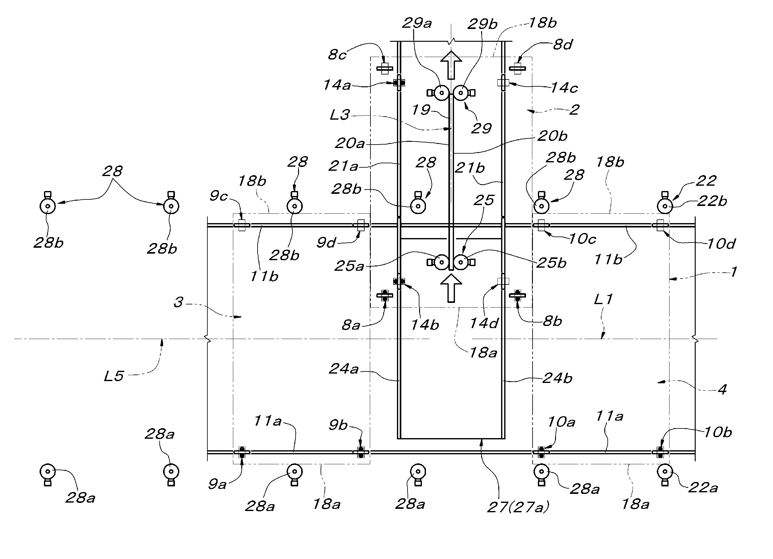
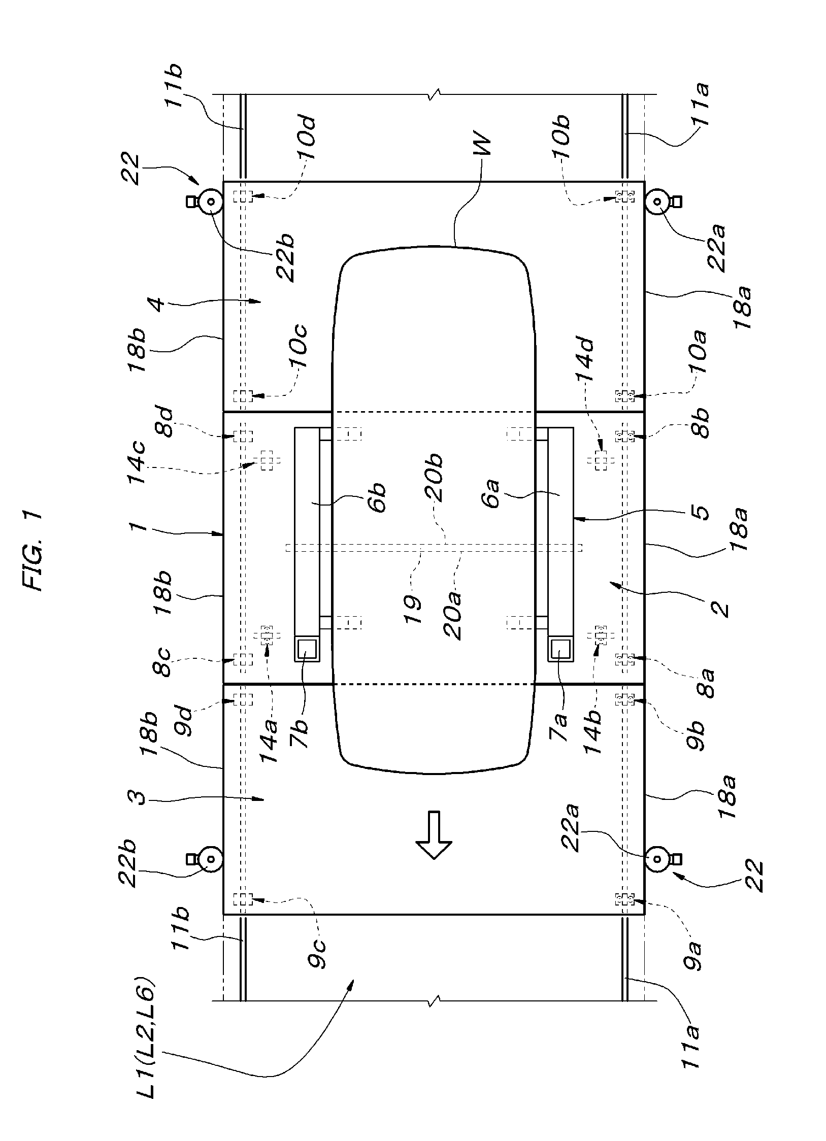
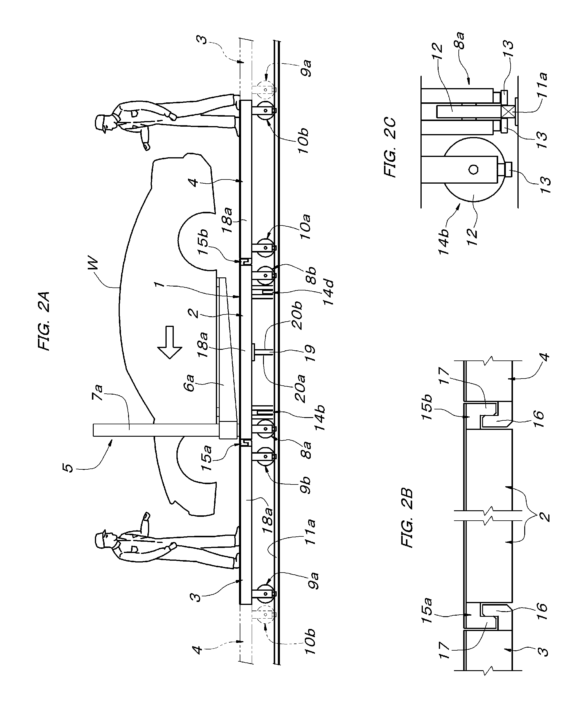
[0032]As shown in FIGS. 1 to 3, a workpiece conveying traveling body 1 in this embodiment is constituted by a workpiece support carriage 2 and two auxiliary carriages 3 and 4 arranged adjacent to the front and rear in a traveling direction of a first conveying path L1 of the workpiece support carriage 2. The workpiece support carriage 2 has such a horizontally long rectangular shape in plan that a width in a left and right lateral direction is greater than a length in the traveling direction of the first conveying path L1. The workpiece support carriage 2 has an upper surface installed with a workpiece supporting means 5 to support a workpiece (an automobile body) W. The workpiece supporting means 5 is such that a pair of left and right elevating support arms 6a and 6b supporting both left and right lateral surfaces of the workpiece W are respectively supported by columns 7a and 7b so as to be vertically movable. The workpiece W supported by the workpiece supporting means 5 has both...


PUM


Abstract

Workpiece conveying equipment provided with a workpiece conveying traveling body composed of a workpiece support carriage and an auxiliary carriage adjacent to at least one of the front and the rear in a traveling direction of the workpiece support carriage, a first conveying path where the workpiece support carriage and the auxiliary carriage travel integrally, a second conveying path where only the workpiece support carriage travels perpendicularly and horizontally with respect to the traveling direction of the first conveying path, and a carriage diverging means provided at a branching point from the first conveying path to the second conveying path so as to separate the workpiece support carriage from the auxiliary carriage and to diverge the workpiece support carriage into the second conveying path perpendicularly and horizontally.

Description

CROSS-REFERENCE TO RELATED APPLICATIONS[0001]The present application is a continuation of pending International patent application PCT / JP2010 / 065257 filed on Sep. 6, 2010 which designates the United States and claims priority from Japanese patent application JP2009-212765 filed on Sep. 15, 2009, the content of which is incorporated herein by reference.FIELD OF THE INVENTION[0002]The present invention relates to workpiece conveying equipment whose workpiece conveying path includes a first conveying path and a second conveying path branched off perpendicularly and horizontally with respect to the first conveying path.BACKGROUND OF THE INVENTION[0003]The above workpiece conveying equipment is known in automobile assembly lines, for example. The automobile assembly lines for example are configured such that on a first conveying path constituting a trim line or final line where work with respect to a relatively low region of the periphery of an automobile body supported on a conveying ca...

Claims


Application Information

Patent Timeline
Patent Type & Authority Patents(United States)
IPC IPC(8): B65G35/06B65G47/52
CPCB62D65/18B65G35/06B65G47/53B61B13/12
Inventor OOE, MASAHIRO
Owner DAIFUKU CO LTD
Why Eureka
Try Eureka