System and method for producing an optically sectioned image using both structured and uniform illumination

a technology of optical sectioning and uniform illumination, applied in the field of imaging, can solve the problems of low signal contrast, inability to slice structures, and many in-vivo structures, and achieve the effect of reducing the number of optical sections

Active Publication Date: 2012-11-13
TRUSTEES OF BOSTON UNIV
View PDF17 Cites 5 Cited by
  • Summary
  • Abstract
  • Description
  • Claims
  • Application Information

AI Technical Summary

Benefits of technology

[0009]The imaging method includes receiving at a processor a first image data set of the real-world object that was illuminated with substantially uniform illumination and receiving a second image data set of the real-world object that was illuminated with substantially structured illumination. The first image data set is processed to produce a high-frequency in-focus data set that eliminates out-of-focus data. The second image data set is processed to produce a low-frequency in-focus data set. The low and high frequency data sets can be combined together and then displayed on a display device producing an image that is the full resolution of the imaging array.

Problems solved by technology

However, some structures, including many in-vivo structures, can not be sliced.
Similarly, it is well known that standard wide-field fluorescence microscopy does not provide optical sectioning for laterally uniform objects.
Wide-field techniques are hampered by their inability to reject out-of-focus background structures, thereby leading to low signal contrast.
One problem with this technique is that it is slow and generally requires several tens of images to produce a final sectioned image of reasonable quality.
One drawback of this technique is that the resultant images often have a striped appearance due to motion related artifacts.
Since the images are obtained sequentially, any movement of the structure to be visualized or the imaging device results in misregistration between images at a processor and therefore, a degradation of the processed image quality.

Method used


Image

  • System and method for producing an optically sectioned image using both structured and uniform illumination
  • System and method for producing an optically sectioned image using both structured and uniform illumination
  • System and method for producing an optically sectioned image using both structured and uniform illumination

Examples


Embodiment Construction

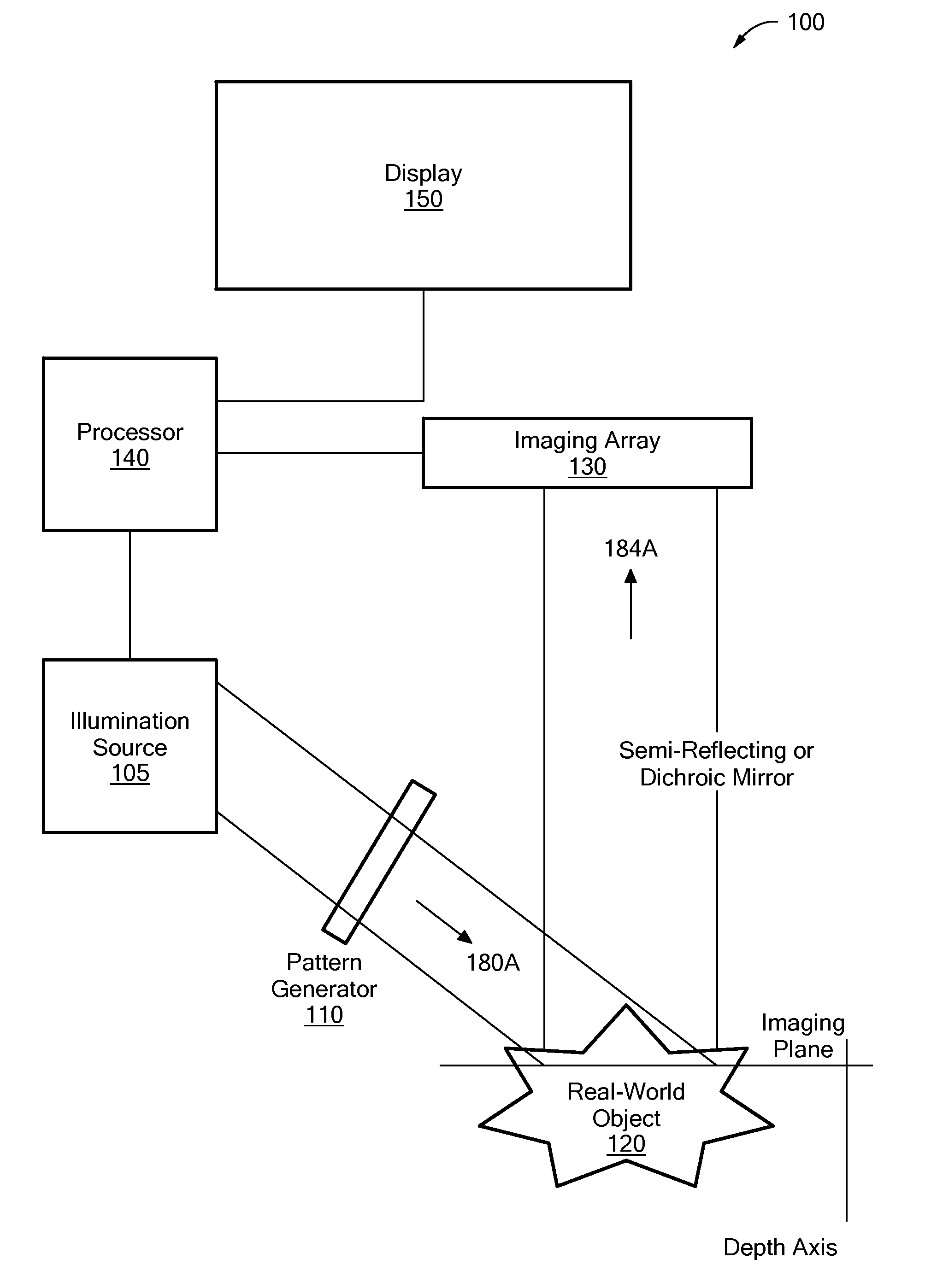
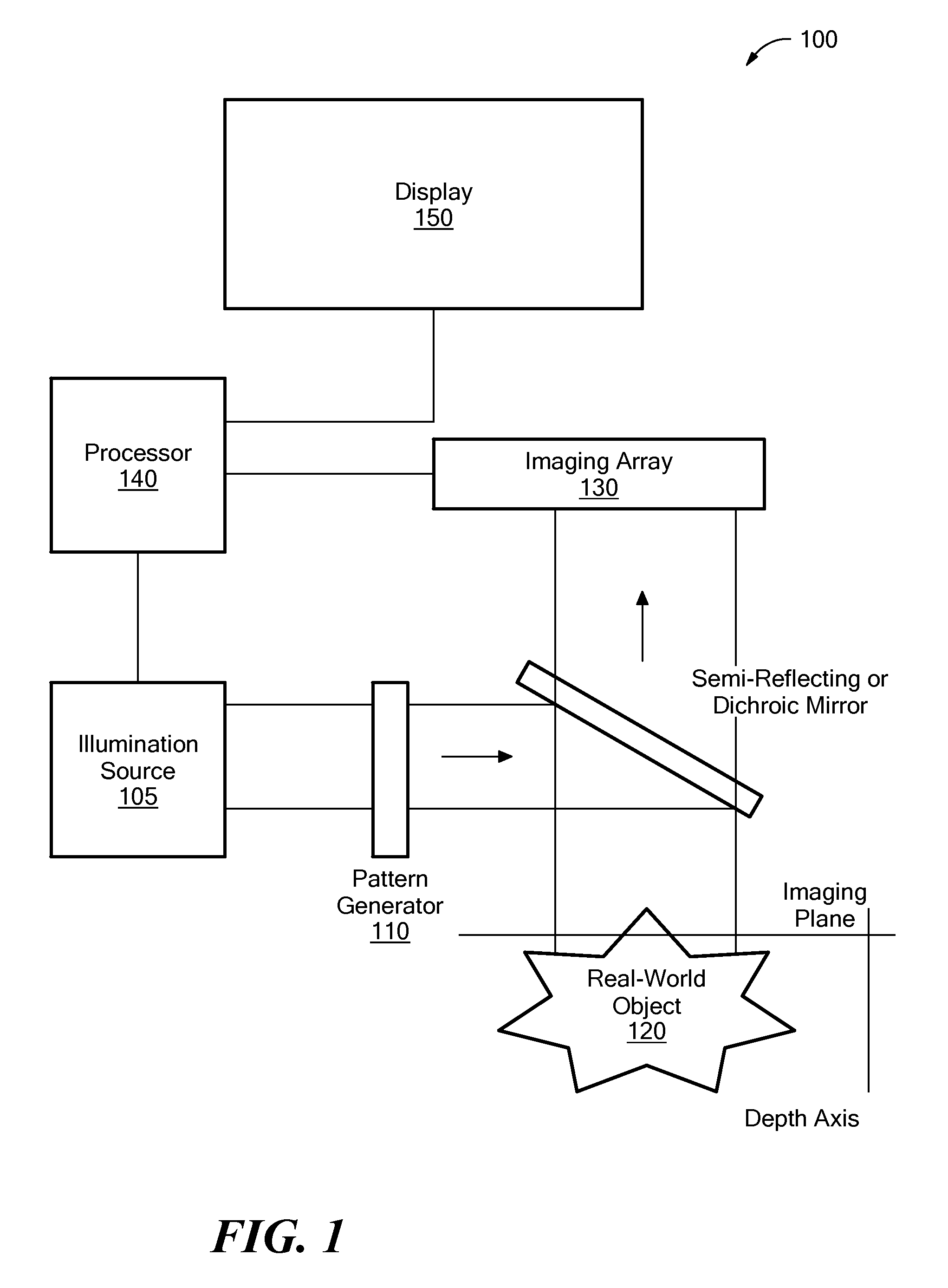
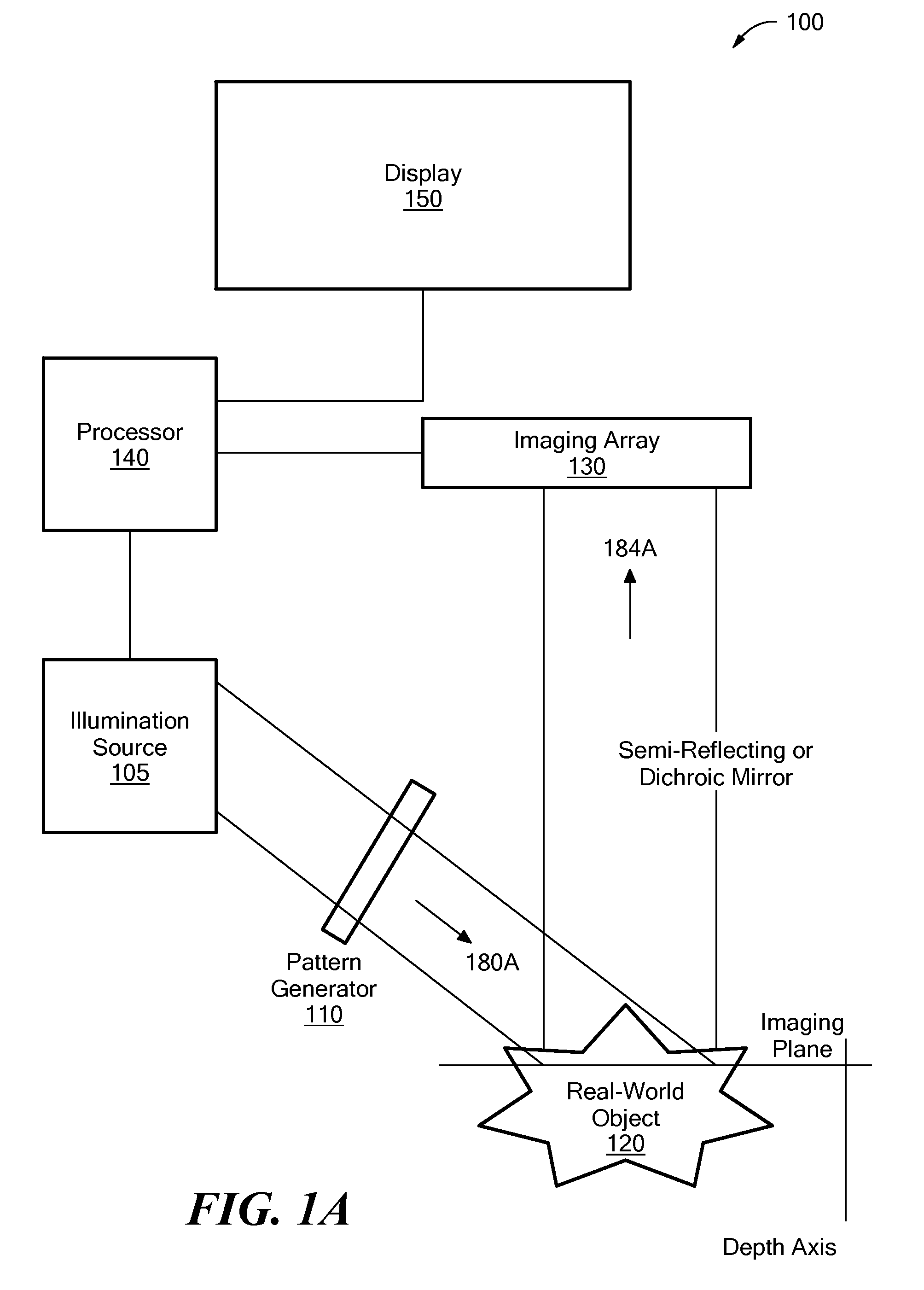
[0027]Definitions. As used in this description and the accompanying claims, the following terms shall have the meanings indicated, unless the context otherwise requires: The term “object signal” shall mean a signal produced by an object such as through reflectance or fluorescence or other energy principle. The terms “imaging system” and “optical imager” shall mean a system that includes at least a detector array (e.g. CCD camera, CMOS camera, etc.). An imaging system may also include one or more sources of illumination. Illumination may result from energy produced by a source (e.g. lamp, laser, diodes etc.). The term “structured illumination” means illumination that produces a spatially varying signal i.e. a signal that exhibits non-uniform contrast. Structured illumination may be spatially random or patterned. The term “uniform illumination” means that the illumination does not significantly vary with space, such that a detector array would not register variations at different spat...


PUM


Abstract

A first image data set of the real-world object is received at a processor where the real-world object was illuminated with substantially uniform illumination. A second image data set of the real-world object is received at the processor where the real-world object was illuminated with substantially structured illumination. A high pass filter is applied to the first-image data set to remove out-of-focus content and retrieve high-frequency in-focus content. The local contrast of the second-image data set is determined producing a low resolution local contrast data set. The local contrast provides a low resolution estimate of the in-focus content in the first-image data set. A low pass filter is applied to the estimated low resolution in-focus data set, thus making its frequency information complementary to the high-frequency in-focus data set. The low and high frequency in-focus data sets are combined to produce an optically-sectioned data set of the real-world object.

Description

PRIORITY[0001]The present patent application is a Patent Cooperation Treaty Patent Application that claims priority from U.S. Provisional Patent Application No. 61 / 130,999 filed on Jun. 5, 2008 entitled “Method of Optical Sectioning with Hybrid Structured and Uniform Illumination Imaging”, which is incorporated by reference herein in its entirety.GOVERNMENT RIGHTS[0002]This invention was made with government support under Contract No. EB007338 awarded by the National Institutes of Health. The Government has certain rights in the invention.TECHNICAL FIELD[0003]The present invention relates to imaging, and more particularly to optically sectioned images.BACKGROUND ART[0004]Typically, whole biological samples that are to be visualized using a microscope are sliced into a thin layer and mounted in order to see the lateral structure. Thus, the sample takes on a two dimensional property by substantially reducing the thickness of the sample, so that the structure within the plane of the sl...

Claims


Application Information

Patent Timeline
Patent Type & Authority Patents(United States)
IPC IPC(8): H04N7/18G06K9/40
CPCG06T5/20G06T5/50G06T5/008G06T2207/10056G06T2207/10068G06T2207/10152G06T2207/20012G06T2207/30024G02B21/06G02B21/16
Inventor MERTZ, JEROMELIM, DARYLCHU, KENGYEH K.
Owner TRUSTEES OF BOSTON UNIV
Why Eureka
Try Eureka