
Thrombosis filter with cover layer

a technology of thrombosis filter and cover layer, which is applied in the direction of dilators, ion implantation coatings, lamination, etc., can solve the problems of thrombotic material dropping off the vessel walls, being transported via the blood stream into narrower vessels, and the inability to exclude the risk of a thrombosis formation in the case of intervention in the blood vessel, etc., to achieve the effect of simple net structure production

Inactive Publication Date: 2012-11-13
ACANDIS
View PDF6 Cites 4 Cited by
  • Summary
  • Abstract
  • Description
  • Claims
  • Application Information

AI Technical Summary

Benefits of technology

"The invention is about improving a net structure used for medical purposes by adding a cover layer. The cover layer can be easily and cost-effectively produced by filling openings in the net structure with a sacrificial material and then depositing a cover layer on top. The cover layer is securely bonded to the net structure and can be modified to meet different needs. The invention also includes a method for depositing a cover layer using vapor deposition or sputtering and galvanic methods. The cover layer can be made from a conductive substrate or a non-conductive substrate with an electrode layer. The invention also includes a method for ensuring a firm bond between the net structure and the substrate using an adhesive bond. The use of a light-sensitive varnish as the adhesive ensures precise adhesion and protection of the net structure during further handling. The invention also includes a method for removing the sacrificial material and the substrate, which can be done mechanically or by dissolving the substrate."

Problems solved by technology

Finally, the risk of a thrombus forming cannot be excluded in the case of interventions in the blood vessels despite the use of state-of-the-art medical engineering.
It is precisely with an intervention of this kind that there is a risk of thrombotic material dropping off the vessel walls and being transported via the blood stream into narrower vessels.
Here, the material can cause a thrombosis or even an embolism, wherein a pulmonary embolism or a stroke can represent a life-threatening emergency.

Method used

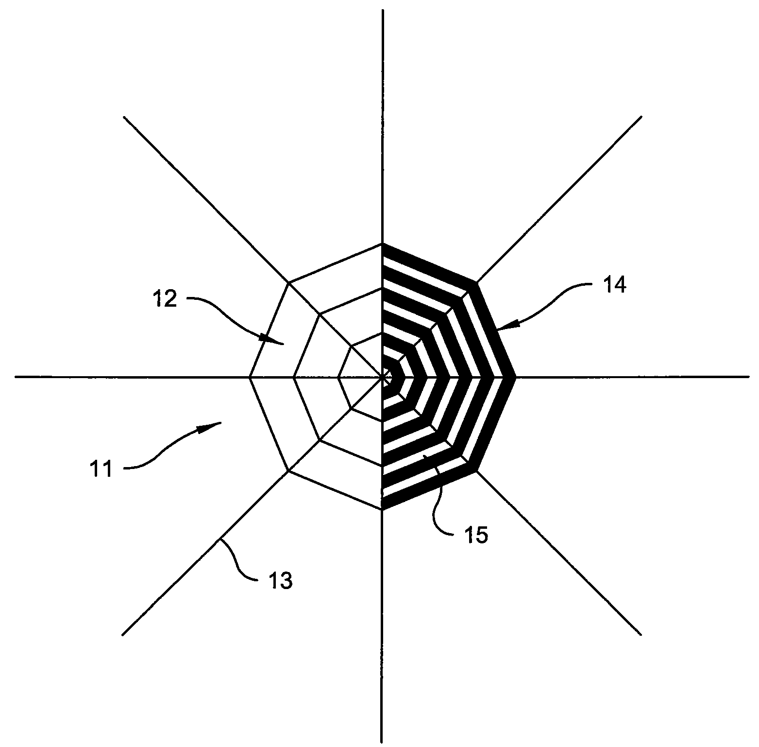
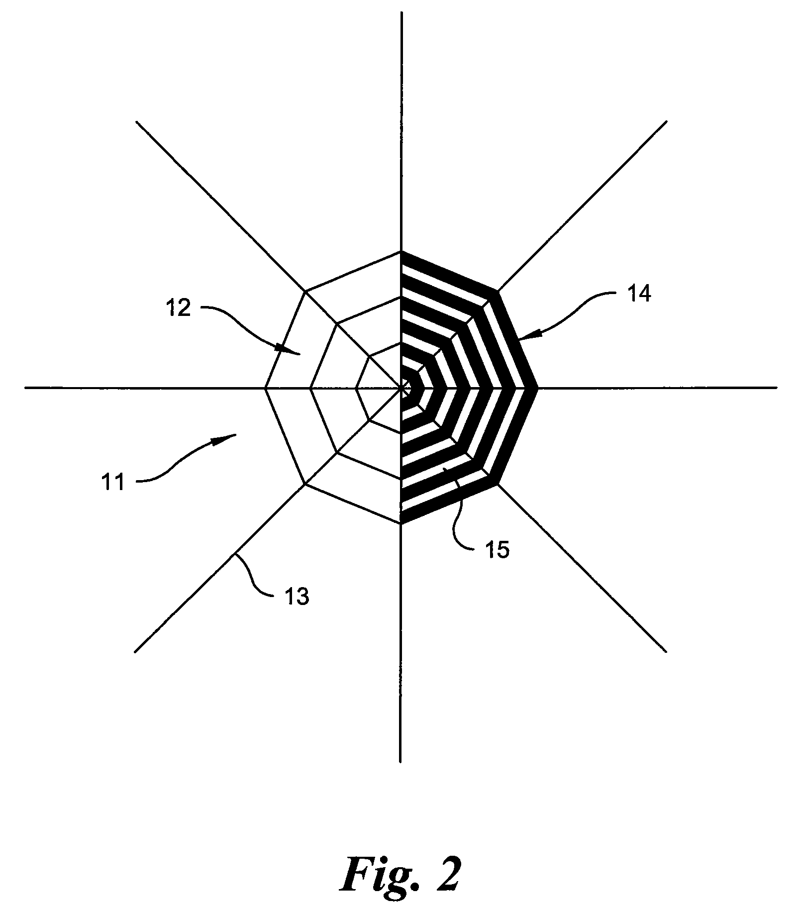

Image

  • Thrombosis filter with cover layer
  • Thrombosis filter with cover layer
  • Thrombosis filter with cover layer

Examples


Embodiment Construction

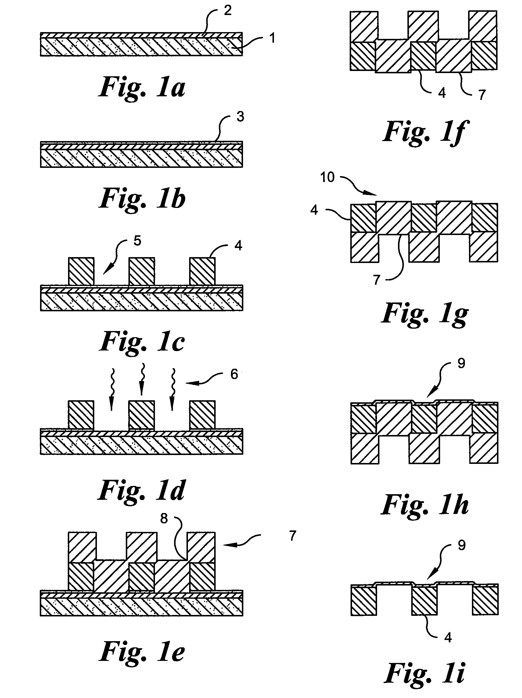
[0022]FIG. 1a is a schematic view of a section through a substrate 1, which is here formed from an Si wafer. This is coated by an electrode layer 2 a few μm thick made of gold. In a following step, shown in FIG. 1b, the gold layer is provided with a layer 3 made of photoresist, which serves as a bonding layer. In FIG. 1c the net structure 4 as the framework of the thrombosis filter is stuck on the adhesive varnish layer 3, wherein the net structure 4 comprises a plurality of openings 5. In the step in FIG. 1d the varnish layer 3 is exposed to light 6 in the region of the openings 5, whereby the region of the varnish layer 3 exposed to light is removed following the development of the gold layer 2.

[0023]Now, a sacrificial material, here copper 7, is deposited on the gold layer 2 and the net structure 4 in a galvanic process. The deposition is performed until the copper 7 fills up the openings 5 and in the transitional region 8 has a bond with the copper 7 deposited on the net structu...


PUM

PropertyMeasurementUnit
elongationaaaaaaaaaa
thicknessaaaaaaaaaa
thicknessaaaaaaaaaa

Abstract

A method is provided for applying a cover layer (9) to a net structure (4) to be used for medical purposes, in particular a thrombosis filter. The net structure (4) is applied to a planar substrate (1) that covers openings (5) of the net structure on one side, wherein the openings (5) across the uncovered side are filled with a sacrificial material (7), in particular copper. The net structure (4) is lifted from the substrate (1). A cover layer (9) is deposited on the surface previously covered by the substrate, and the sacrificial material (7) is removed.

Description

CROSS-REFERENCE TO RELATED APPLICATIONS[0001]This application is a Section 371 of International Application No. PCT / EP2007 / 007455, filed Aug. 24, 2007, which was published in the German language on Feb. 28, 2008, under International Publication No. WO 2008 / 022799 A2 and the disclosure of which is incorporated herein by reference.BACKGROUND OF THE INVENTION[0002]The present invention relates to a method for applying a cover layer to a net structure to be used for medical purposes, in particular a thrombosis filter. The invention also relates to a thrombosis filter provided with a cover layer according to this method.[0003]Net structures of this kind can have different applications in medicinal treatments. They can, for example, be used as vessel supports, in particular as stents. In addition to their use as permanent implants, the net structures according to the invention can be used as thrombosis filters, for example during vessel widening (angioplasty) via a cardiac catheter. Final...

Claims


Application Information

Patent Timeline
Patent Type & Authority Patents(United States)
IPC IPC(8): C25D1/00A61L33/00B29C37/02
CPCA61F2/01A61L31/022A61L31/088A61L31/14A61F2230/008A61F2002/018A61F2230/005A61F2/0105
Inventor QUANDT, ECKHARDZAMPONI, CHRISTIANESCHMUTZ, CLEMENS
Owner ACANDIS
Learn More