Electronic device and method for attaching light guide lens

a technology of electronic devices and light guides, applied in the field of electronic devices, can solve the problems of difficulty in disassembling and recycling light guides, inability to easily attach light guides, and tendency toward higher component costs, and achieve the effect of simple and low-cost attachmen

Active Publication Date: 2012-11-13
TEAC CORP
View PDF7 Cites 2 Cited by
  • Summary
  • Abstract
  • Description
  • Claims
  • Application Information

AI Technical Summary

Benefits of technology

[0008]Accordingly, the present invention aims at providing an electronic device that enables simpler, lower cost attachment of a light guide lens and an attachment method.
[0012]In yet another preferred mode, the electronic device further comprises a projecting member that protrudes from the rim on the back surface side of the insert hole, that allows entry of the light guide lens from the back surface side, and opposes in close proximity to the back surface of the light guide lens entered from the back surface side, thereby preventing detachment of the light guide lens. In this case, the light guide lens preferably has a lens and thin flanges that extend from the rim of the back surface of the lens to the outside, and indentations for accommodating the respective flanges are preferably formed along the rim of the insert hole on the back side of the design panel.
[0014]According to the present invention, the light guide lens is attached to the insert hole by elastically deforming the rim of the insert hole. Therefore, the light guide lens can be attached more easily and at lower cost.

Problems solved by technology

However, the technique requires a welding facility and encounters a problem of the inability to easily attach the light guide lens.
Further, since a once-welded light guide lens cannot be removed, difficulty is encountered in disassembling and recycling the light guide lens.
However, since a special material, like a soft light transparent material, is utilized, there has been a problem of a tendency toward higher component costs.

Method used


Image

  • Electronic device and method for attaching light guide lens
  • Electronic device and method for attaching light guide lens
  • Electronic device and method for attaching light guide lens

Examples


second embodiment

[0060]First, the light guide lens 16 used in the second embodiment is described by reference to FIGS. 7A to 7C. FIG. 7A is a front view of the light guide lens 16; FIG. 7B is a drawing of the light guide lens acquired along its minor axis; and FIG. 7C is a drawing of the light guide lens acquired along its major axis.

[0061]The light guide lens 16 of the second embodiment is roughly divided into a lens 36 acting as a lens and the flanges 38 bulging outside from the neighborhood of the lens 36. When viewed from the front, the lens 36 assumes a horizontally long, substantially oblong shape. Each of four side surfaces of the lens 36 has a taper directed outside with a nearer approach to the back side, so that the lens becomes smaller with an increasing distance from its back surface to its front surface. When viewed from another aspect, the lens 36 assumes a substantially truncated pyramidal shape such that the oblong shape becomes increasingly smaller in size from its back surface to i...

first embodiment

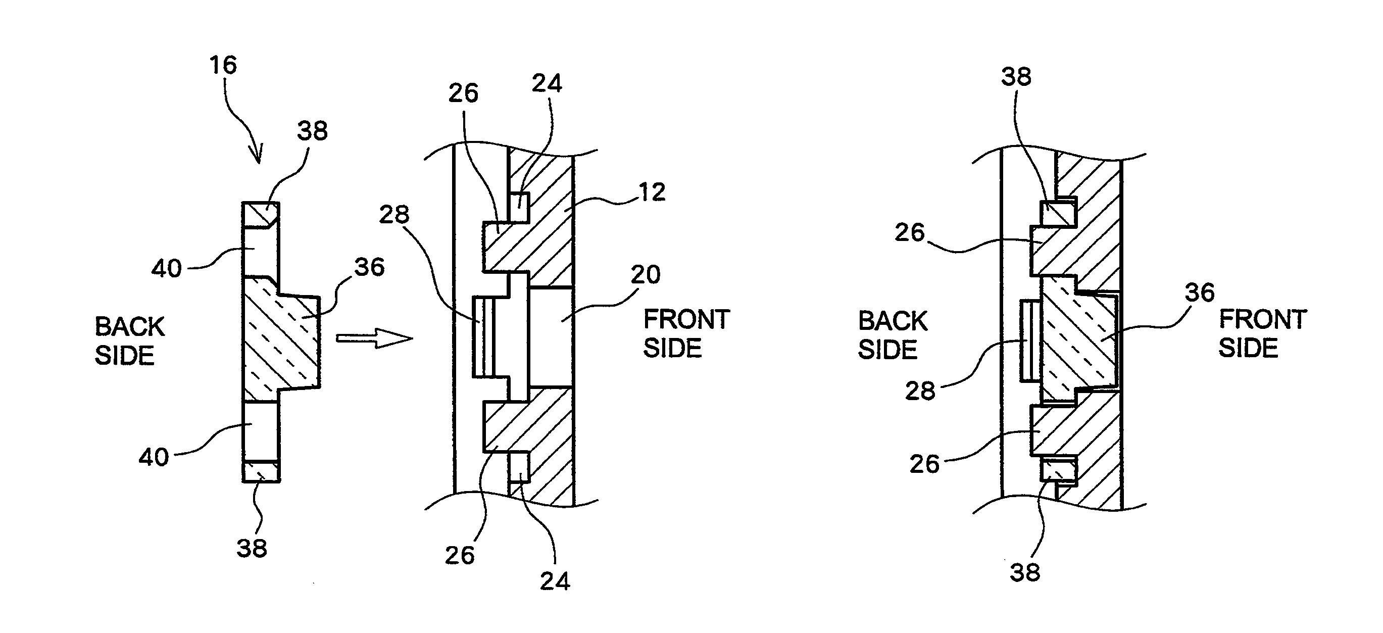
[0074]Specifically, in the present embodiment, detachment of the light guide lens 16 to both the front side and the back side is effectively prevented as in the When compared with the related art, assembly of the light guide lens 16 can be facilitated, so that component costs can be curtailed.

[0075]Further, even in the present embodiment, the once-attached light guide lens 16 can be detached. Specifically, when detachment of the light guide lens is required after the light guide lens 16 has been attached to the insert hole 20, the light guide lens 16 is pressed from the front side to the back side while the projecting members 28 are outwardly deflected by exertion of outward-oriented force, whereby the light guide lens 16 can be detached from the design panel 12. As a consequence, wasteful discarding of the light guide lens 16 and the design panel 12 can be lessened, so that manufacturing costs can be curtailed further.

[0076]Moreover, since the present embodiment employs a configur...


PUM

PropertyMeasurementUnit
elastic deformationaaaaaaaaaa
opening widthaaaaaaaaaa
soft light transparentaaaaaaaaaa

Abstract

An electronic device includes a design panel 12 made of a resin and a light guide lens 16 that is attached to the design panel 12 so as to guide light from a light source to the outside. An insert hole 20 that is a through hole whose shape is commensurate with the light guide lens 16 is formed in the design panel 12. The light guide lens 16 is inserted into the insert hole 20 by elastically deforming a rim of the insert hole 20 when the light guide lens 16 is pushed into the insert hole 20, to thus be attached to the design panel 12. Auxiliary grooves 22 that promote elastic deformation are formed in a neighborhood of the rim of the insert hole 20.

Description

[0001]This application claims priority to Japanese Patent Application No. 2010-289595, filed on Dec. 27, 2010, which is incorporated herein by reference in its entirety.TECHNICAL FIELD[0002]The present invention relates to an electronic device equipped with an indicator as well as to a method for attaching a light guide lens constituting the indicator to a design panel.BACKGROUND ART[0003]A hitherto widely known electronic device is equipped with an indicator that displays a status of the electronic device (e.g., activation / deactivation of the power) to a user by means of a lighting condition. Many of the indicators are equipped with a lightguide lens that guides light from a light source to the outside. The light guide lens is usually fitted into an insert hole opened in a design panel.[0004]If the thus-attached light guide lens remains simply inserted into the insert hole, the lens will often detach itself from the insert hole. According to JP 2008-152844 A, after a light guide le...

Claims


Application Information

Patent Timeline
Patent Type & Authority Patents(United States)
IPC IPC(8): F21V7/04G02B7/02
CPCG06F1/1613G06F1/181G06F1/1656Y10T29/49002
Inventor FUJIMURA, NOBUHIKO
Owner TEAC CORP
Why Eureka
Try Eureka