Cellular base station augmentation system and method

a cellular base station and augmentation technology, applied in the field of wireless communication systems, can solve the problems of occupying additional space for extra antenna arrays, and achieve the effects of improving transmit and receive performance, facilitating the augmentation of cellular base station systems, and improving wireless communications systems

Inactive Publication Date: 2006-01-17
CELLETRA
View PDF16 Cites 1 Cited by
  • Summary
  • Abstract
  • Description
  • Claims
  • Application Information

AI Technical Summary

Benefits of technology

[0009]The present invention is provided to improve wireless communications systems. More specifically, the present invention is provided to facilitate the augmentation of cellular base station systems, for example, improving the transmit and receive performance of a given base station and its associated cell or sector, or providing new cellular technology (for example, CDMA) capabilities to an existing base station.
[0014]Using dual transmission at both space-diversity antennas can also be beneficial for operators who wish to double the total number of served carriers without having to replace the power amplifier unit. By dividing the served carriers into two groups, with each group containing half the number of carriers having a relatively small frequency spacing, and directing each group to another active antenna array, a simpler and lower cost power amplifier can be used.
[0015]The augmentation can further be extended for Time Division Multiple Access (TDMA) systems, such as GSM and IS-136 by adding a switch between the RF front-end active antenna array and the channel cards. This configuration will provide some forward link performance benefit for TDMA systems, similar to time-diversity on CDMA.

Problems solved by technology

Extra antenna arrays may take up additional space, or may be unacceptable (and may also be a violation of local laws, regulations or ordinances).

Method used


Image

  • Cellular base station augmentation system and method
  • Cellular base station augmentation system and method
  • Cellular base station augmentation system and method

Examples


Embodiment Construction

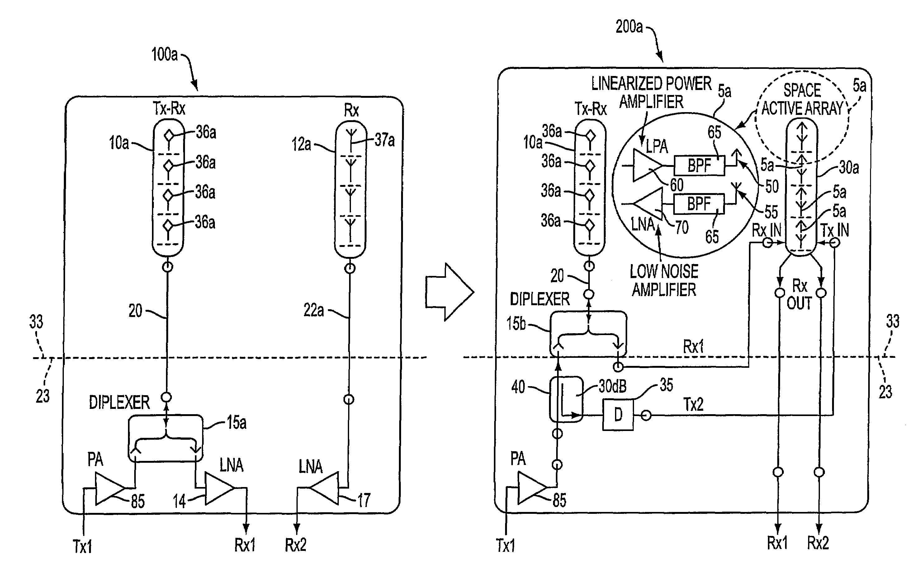
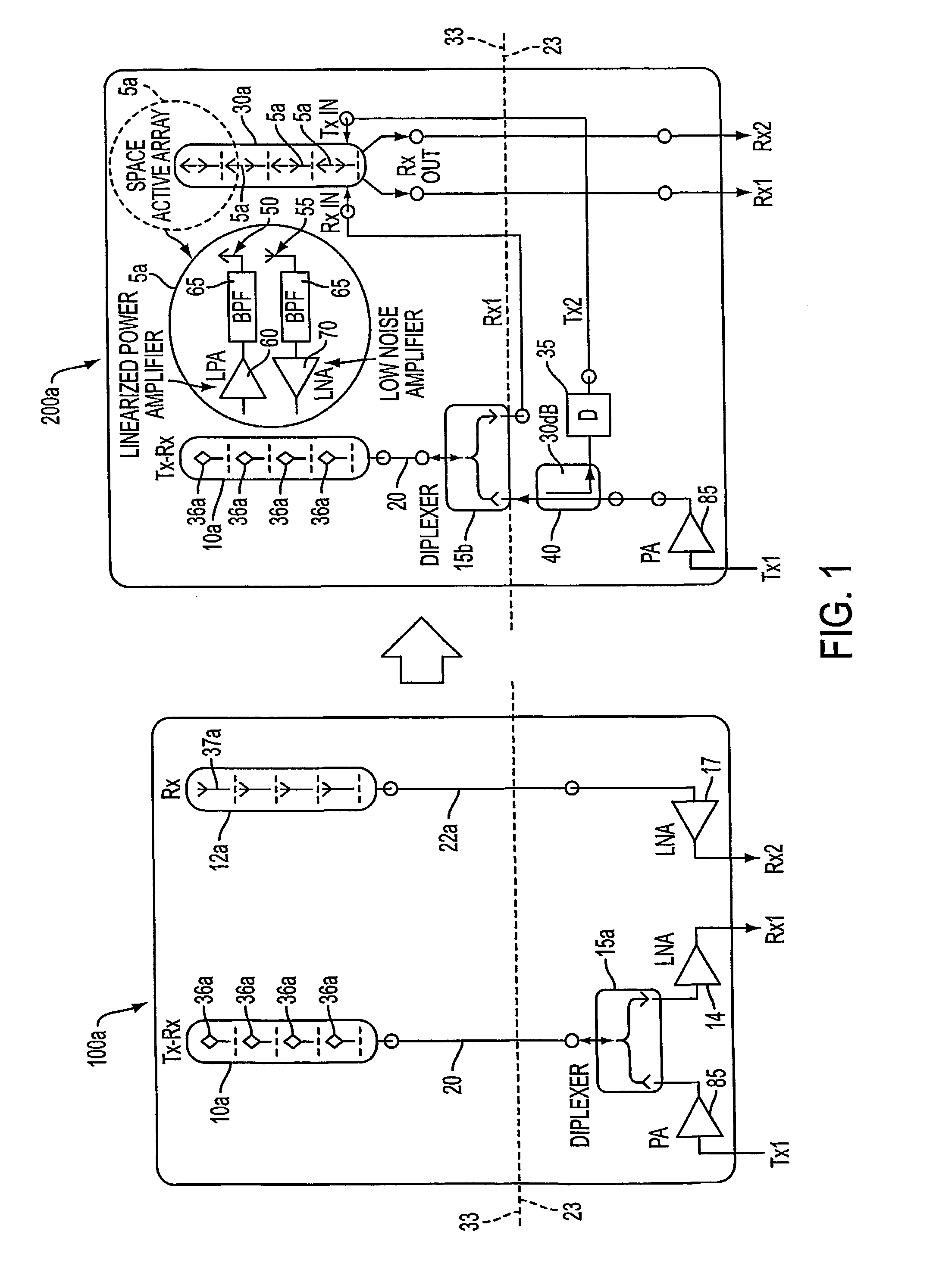
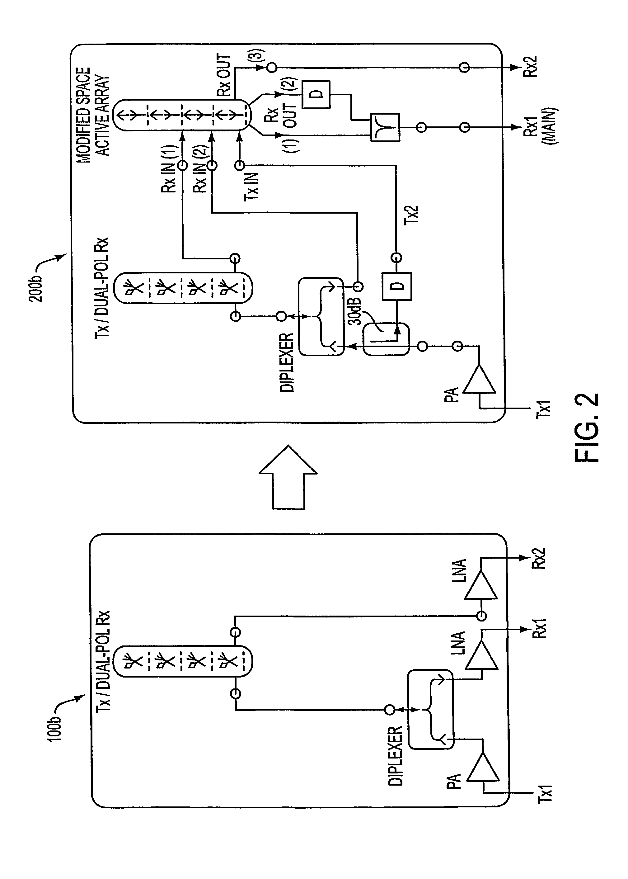
[0027]An existing base station antenna arrangement may be augmented by adding a new antenna array and / or replacing an existing antenna array with a new antenna array. FIGS. 1–7 illustrate various embodiments of such augmentations of existing base station antenna arrangements 100a–g with a new antenna array 30a–g. The new antenna array 30a–g may comprise an active antenna array, which includes an active radiator unit 5a or 5b having both receive and transmit antenna elements. By way of example, the circled portion 5a shown in FIG. 1 depicts an exemplary structure of the active radiator unit 5a that may be utilized in the active antenna arrays 30a–c of FIGS. 1–3.

[0028]FIG. 1 illustrates an augmentation method that modifies an existing base station antenna arrangement 100a, which comprises a main antenna array 10a and a secondary antenna array 12a, by replacing the secondary antenna array 12a with a new antenna array 30a, which may be active or passive. Namely, augmentation of the base...


PUM


Abstract

A method and apparatus for augmenting an existing base station for cellular communications, especially when the existing base station includes a main antenna and a diversity antenna. The method comprising replacing the diversity antenna array with a new diversity antenna array comprising both receive and transmit elements; installing a switching matrix in the signal path between the base station and the transmit element of both the new diversity antenna array and the main antenna array; and switching the transmission of data between the transmit elements of the main antenna array and the diversity antenna array.

Description

RELATED APPLICATION DATA[0001]Priority is hereby claimed to U.S. Provisional Patent Application Ser. No. 60 / 177,653, entitled Cellular Base Station Augmentation and Method, filed Jan. 27, 2000, the content of which is hereby expressly incorporated by reference herein, in its entirety.BACKGROUND OF THE INVENTION[0002]1. Reservation of Copyright[0003]This patent document contains information subject to copyright protection. The copyright owner has no objection to the facsimile reproduction by anyone of the patent document or the patent, as it appears in the U.S. Patent and Trademark Office patent files or records, but otherwise reserves all copyright rights whatsoever.[0004]2. Field of the Invention[0005]The present invention, in certain aspects, relates to wireless communication systems. In other aspects, the present invention relates to augmenting the capabilities of existing base station antenna systems.DESCRIPTION OF BACKGROUND INFORMATION[0006]Existing and operational base statio...

Claims


Application Information

Patent Timeline
Patent Type & Authority Patents(United States)
IPC IPC(8): H04M1/00H01Q3/22H04B1/02H01Q1/24H04B7/04H04B7/06H04B7/10H04W16/24
CPCH01Q1/246H04B7/04H04B7/0678H04B7/10H04B7/0671H04W16/24H04B7/02
Inventor SHAPIRA, JOSEPHLEMSON, PAUL HLEVY, DAVID
Owner CELLETRA
Why Eureka
Try Eureka