Marine thrust wings

Inactive Publication Date: 2009-02-19
WALKER JOHN G
View PDF1 Cites 0 Cited by
  • Summary
  • Abstract
  • Description
  • Claims
  • Application Information

AI Technical Summary

Benefits of technology

[0006]The present invention is intended to provide a simpler and lower cost solution to the challenges of high-thrust, low-drag thrust wing design. It is based on a single symmetrical aerofoil fitted with a le

Problems solved by technology

However, the known wingsail has a r

Method used


Image

  • Marine thrust wings
  • Marine thrust wings
  • Marine thrust wings

Examples


Embodiment Construction

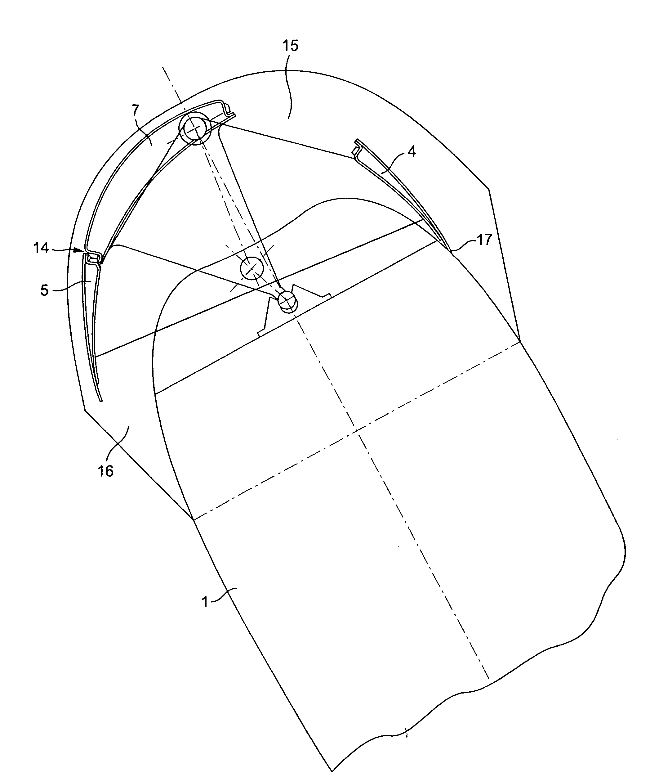
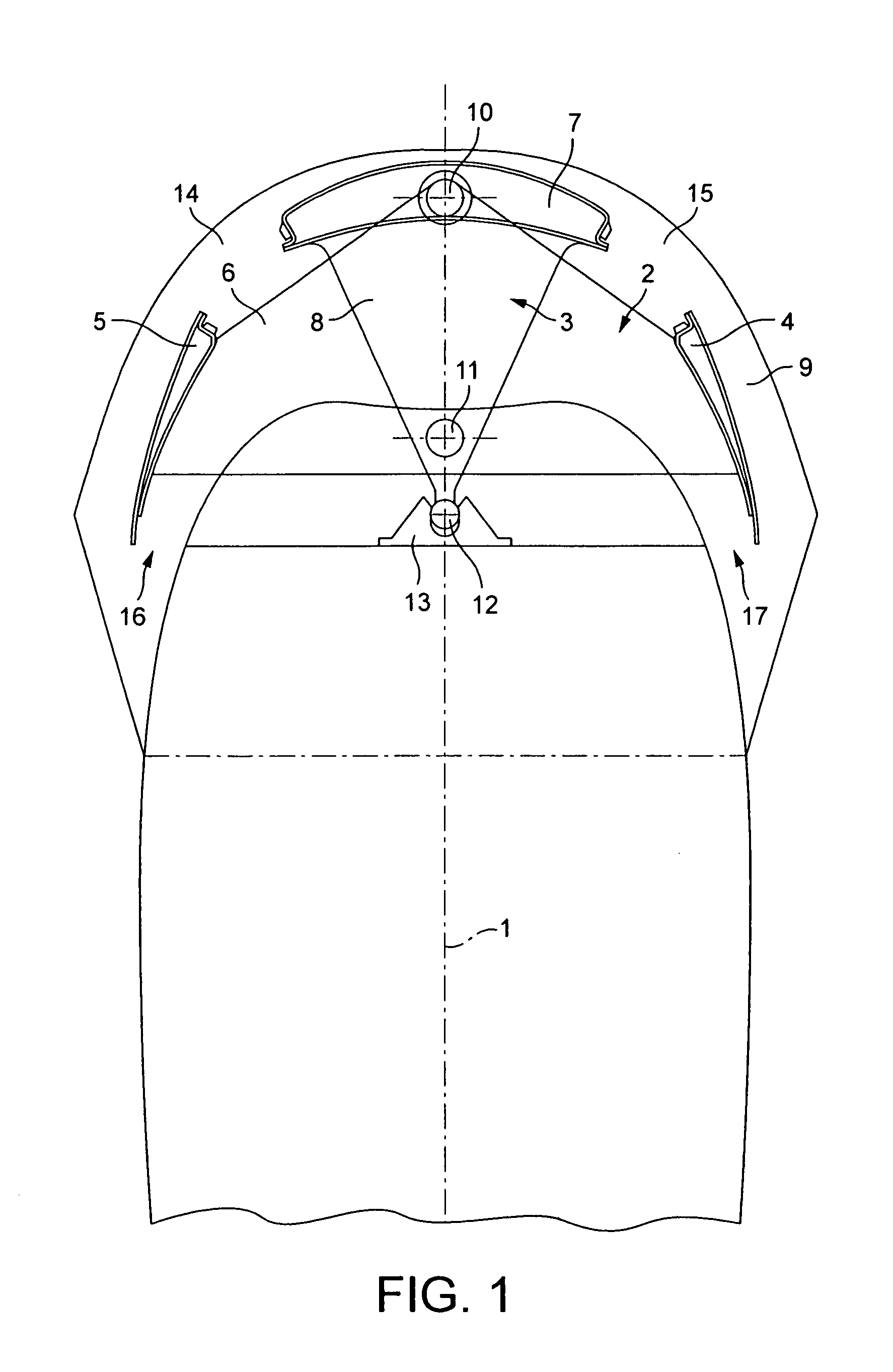
[0021]The invention will now be described by reference to the drawings. In FIGS. 1 to 5 the wind should be considered as blowing “down the page”, and the phrases “left of wind” and “right of wind” are used to define elements, areas or actions when looking into the wind, which or in this description will be regarded as “up the page”.

[0022]FIG. 1 shows a horizontal cross section through the thrust wing according to this invention, shown with its three principal elements configured to be completely symmetrical about the plane of symmetry of the main aerofoil 1, so that if the thrust wing is aligned to the relative wind at zero angle of attack no cross-wind force will be reacted on to the vessel on which the wingsail is installed. Two further principal leading edge slot and slat elements are:—a twin vane assembly 2, consisting of two vanes 4 and 5 and two hinge plates, one at each end, 6, and a single vane assembly 3, consisting of a single vane 7 and two hinge plates 8, one at each end...


PUM


Abstract

A wingsail assembly comprises a main symmetrical aerofoil which is freely rotatable about an upright axis and a control vane which is settable about an upright axis spaced from the axis of the main aerofoil to cause the main aerofoil to adopt an angle of attack to the direction of the wind. A pivoted aerodynamic slot-forming vane assembly is rotatable in response to wind pressure to open and close respective slots, one on each side of the leading region of the main aerofoil. A linkage inhibits movement of the slot-forming vane assembly away from a neutral position when the control vane is set to a neutral position.

Description

FIELD OF THE INVENTION[0001]This invention relates to marine thrust wings. Such marine thrust wings are aerodynamic thrust devices broadly similar in principle to the wings of aircraft, but arranged upright (i.e. vertically) instead of horizontally, designed to propel and help to manoeuvre marine craft.BACKGROUND TO THE INVENTION[0002]A typical design constraint, for marine craft other than certain specialised racing or record breaking boats, is that, unlike the wings of an aircraft, thrust wings must work as well with the wind coming from one side, or tack, as when it comes from the other side. In an aircraft, that is equivalent to the design of a plane capable of exactly the same performance upside down as right way up. In the specialised example of planes specifically designed for aerobatics, this is indeed sometimes the case.[0003]This means that a thrust wing aerofoil section for marine use must be symmetrical about a vertical plane, or that it must be constructed from more or ...

Claims


Application Information

Patent Timeline
IPC IPC(8): B63H9/04
CPCB63H9/0607B63H9/061
Inventor WALKER, JOHN G.
Owner WALKER JOHN G
Why Eureka
Try Eureka