
Flame ionization detector

Inactive Publication Date: 2012-11-06
BAYER AG +1
View PDF11 Cites 4 Cited by
  • Summary
  • Abstract
  • Description
  • Claims
  • Application Information

AI Technical Summary

Benefits of technology

[0017]In an advantageous embodiment, the nozzles for the gases are formed as a buried structure and are covered by at least one further substrate. In this way, it is possible to achieve a symmetrical arrangement of the nozzles.

Problems solved by technology

A problem with flame ionization detectors is that it is necessary to supply oxyhydrogen gas, a highly explosive mixture of oxygen and hydrogen.
Since the flame burns in open space, the result can be influenced by turbulence and contamination.
An additional disadvantage is that the glass tube must be adhesively bonded, and therefore the detector cannot be produced entirely by the methods of microsystem technology, so that its structure is elaborate and expensive and unsuitable for mass production.
Other previously known flame ionization detectors with a small design have the disadvantage that they cannot be produced, or cannot be produced entirely, by the methods of microsystem technology (U.S. Pat. No. 5,576,626; WO 2006 / 000099 A1).

Method used


Image

  • Flame ionization detector
  • Flame ionization detector
  • Flame ionization detector

Examples


Embodiment Construction

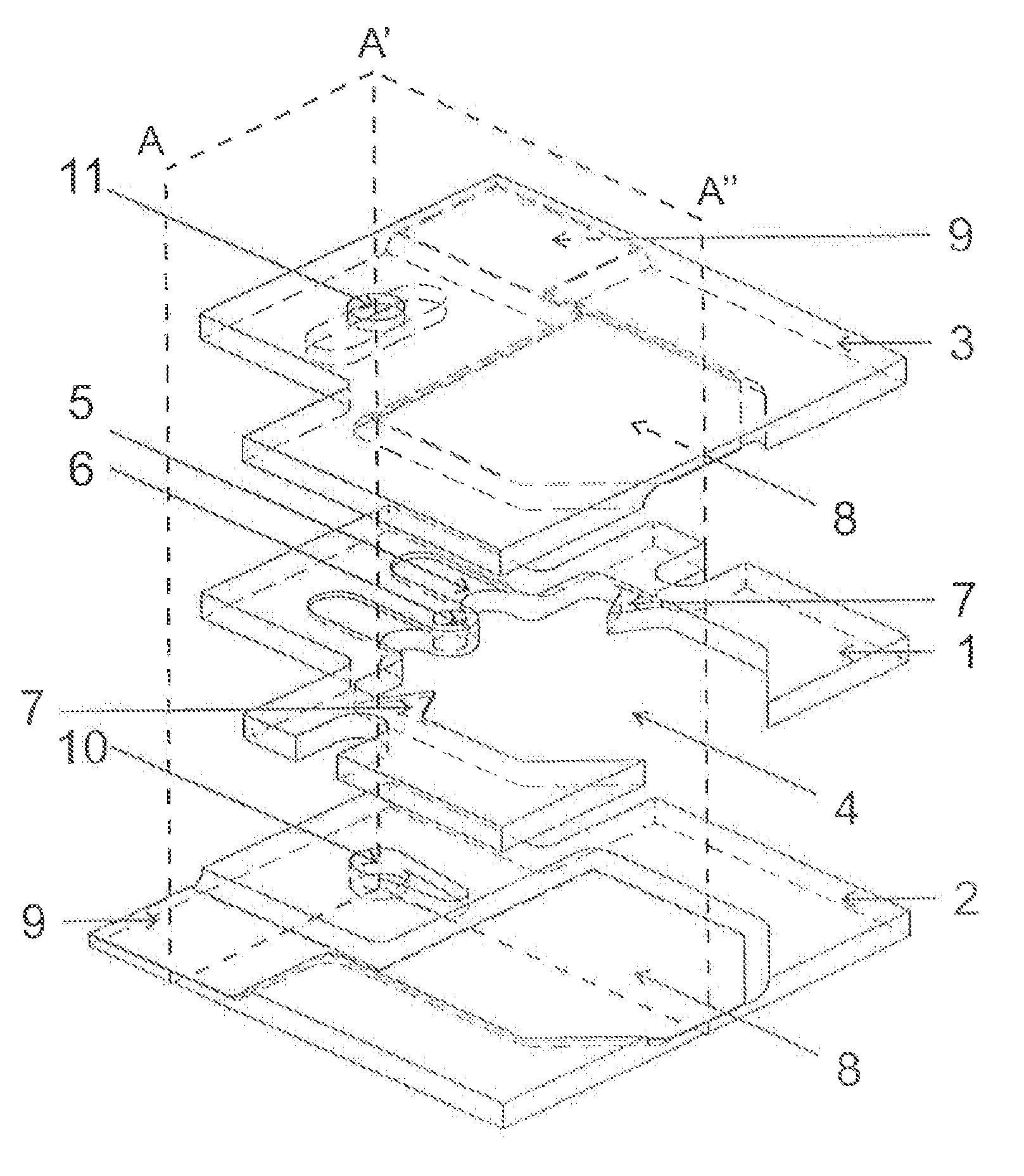
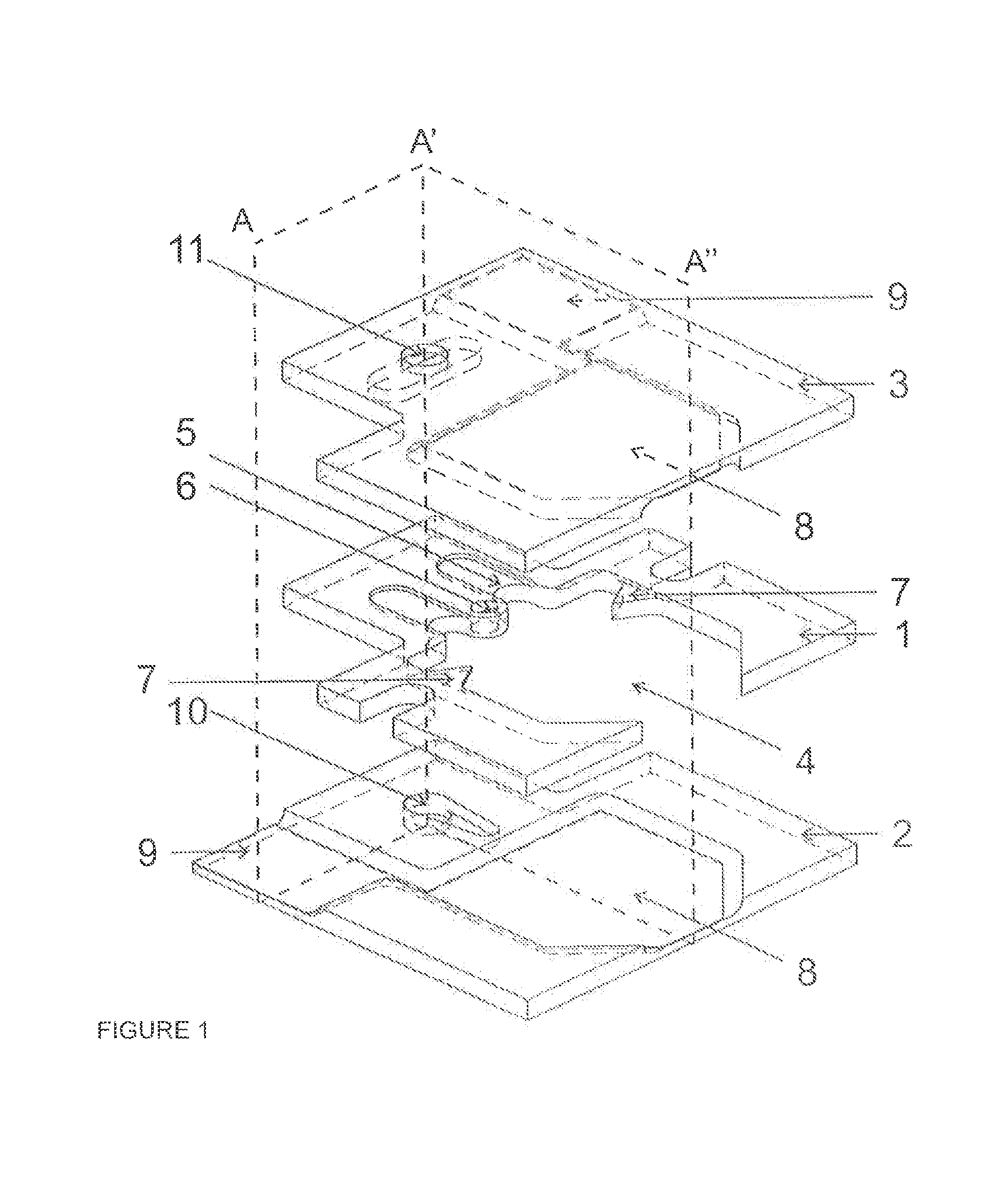
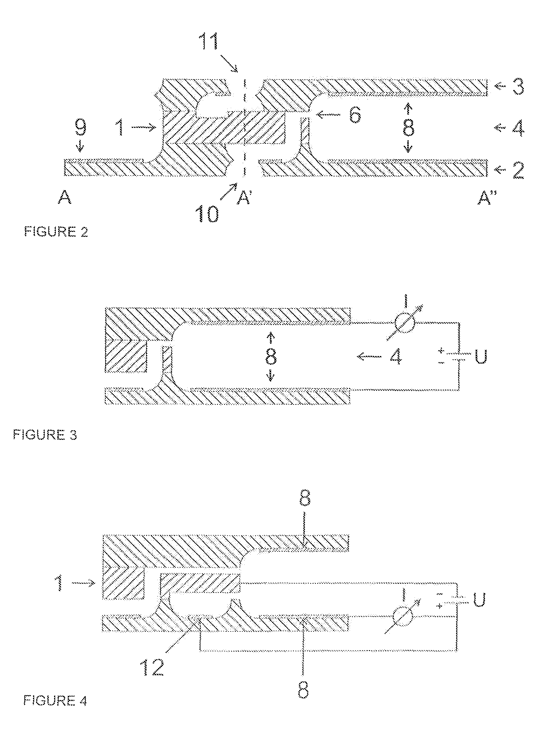
[0026]FIG. 1 shows an exploded view of an inventive embodiment of the flame ionization detector. It comprises three substrates: a central substrate 1 made of silicon, and a lower substrate 2 and an upper substrate 3 which are made of Pyrex glass. A part of the combustion chamber 4, the sample gas nozzle 5 and the combustible gas nozzle 6 are excavated in the central substrate 1 by known microsystem technology methods. Acute projections 7, which extend into the combustion chamber 4 in the vicinity of the nozzles 5, 6, can have a high-voltage pulse applied to them for ignition.

[0027]The lower substrate 2 and the upper substrate 3 are provided with trough-shaped recesses in the region of the combustion chamber 4, and these are provided with a reflective metallization 8. The metallization 8 is connected to bonding lands 9, through which the electrical connection can take place. The substrate 2 lying underneath in the figures also comprises a combustible gas inlet 10, while the upper sub...


PUM


Abstract

The flame ionization detector, which comprises a supply and an ignition device (7) for the combustible gas, a supply for the sample gas, a combustion chamber (4) in which the sample gas is ionized by the flame, and electrodes (8, 1) to which a voltage is applied in order to generate and measure the ion current, is distinguished in that it is constructed as an integrated planar system of at least three parallel platelet-like substrates (1, 2, 3) which are connected to one another and are processed by microsystem technology methods, with a central substrate (1) comprising nozzles (5, 6) for the gases and the ignition device (7) and a recess which forms a part of the combustion chamber (4), is completed by recesses in the neighboring substrates (2, 3) and is essentially closed together with the nozzle region by these substrates (2, 3), and the neighboring substrates (2, 3) comprise supply channels (10, 11) for the gases.

Description

[0001]This is an application filed under 35 USC §371 of PCT / EP2008 / 006781, claiming priority to EP 07018014.6 filed Sep. 13, 2007.BACKGROUND OF THE INVENTION[0002]The invention relates to a flame ionization detector (FID) which comprises a supply and an ignition device for the combustible gas, a supply for the sample gas, a combustion chamber in which the sample gas is ionized by the flame, and electrodes to which a voltage is applied in order to generate and measure the ion current.[0003]Flame ionization detectors are used to detect and measure volatile organic compounds in gaseous samples. The measurement is based on the chemical ionization of organic substances, which are pyrolyzed in an oxyhydrogen gas flame. An ionization reaction of the carbon atoms contained in the substance takes place:CH+O→CHO++e−[0004]When a voltage is applied to an electrode pair arranged at the edge of the flame, an ion current flows which can be measured and used to detect the organic compounds. If the ...

Claims


Application Information

Patent Timeline
IPC IPC(8): G01N27/62
CPCG01N27/626G01N30/68G01N30/6095
Inventor JORG, MULLERKUIPERS, WINFRED
Owner BAYER AG
Learn More