
Adjustable method and apparatus for laying, leveling and compacting road shoulders

Active Publication Date: 2012-10-30
BONNELL INDS
View PDF22 Cites 23 Cited by
  • Summary
  • Abstract
  • Description
  • Claims
  • Application Information

AI Technical Summary

Benefits of technology

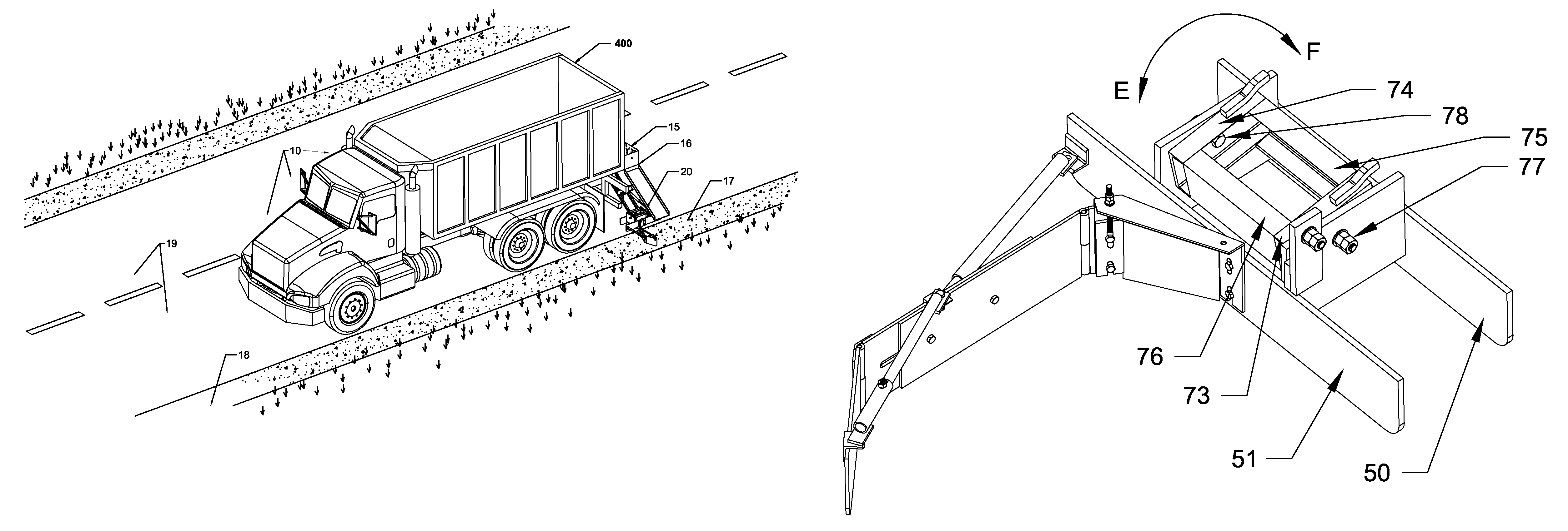
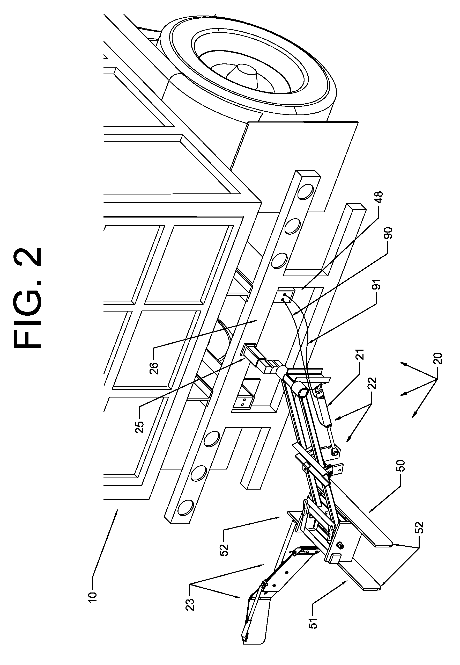
[0009]On the forward and rearward sides of the rectangular enclosure there are second and third pivot holes, respectively. Pivotally mounted by pivot pins into these second and third pivot holes are a forward and rearward support plates extending downward. Fixedly attached to the support plates are an inner and outer runner, both of which are rounded in the front and rear for ease of following the roadway surface. When viewed from the rear of the truck, this arrangement allows for the runners to pivot in a left and right motion to relative to the roadway in relation to the truck. This also allows the leveling apparatus to be pivoted into a vertical position when the apparatus is being transported.
[0010]A support brace is fixed to the outer runner at one end of the support brace and to the first part of the leveling plate at the other end through vertically slotted holes in the support brace. There is a height adjusting plate with two through holes and a threaded rod attached to the top of the height adjusting plate. The threaded rod going through an adjusting bar that is fixed to the top of the support brace. A nut on the threaded rod allows a user to raise or lower the height adjusting plate, and thereby the first part of the leveling blade, as a means for adjusting the height of the leveling plate and thereby the height of the aggregate above the road. The aggregate is later compacted evenly with the road way. The support brace being taller than the runners and leveling plate in order to keep the aggregate onto the shoulder and off of the road. The first part of the leveling plate is mounted to the support brace and height adjusting plate at an obtuse angle to the runners with two fasteners, one fastener going through a lower through hole and the other fastener going through an upper horizontally slotted hole in the first part of the leveling plate. By loosening the two fasteners, the first part of the leveling plate can be rotated about the lower fastener and within the range defined by the upper horizontal slot in order to adjust the pitch of the leveling plate to a desired angle. The first part of the leveling plate is hinged proximate to where the support brace is attached to the first part of the leveling plate. There is at least one and preferably two fastening mechanisms, such as a bolt or the like mounted to the first part of the leveling plate.
[0011]The second part of the leveling plate has the same height as the first part of the leveling plate but also includes an elongated horizontal slot in the second part of the leveling plate which is adjustably engaged with the fastening mechanisms on the first part of the leveling plate. This allows the operator to adjust the width of the leveling plate assembly and thereby adjust the width of the shoulder being laid. At the outer end of the second part of the leveling plate there is a retaining plate hingedly attached to the outer end. A first adjustable pivotable telescoping length rod connects the outer end of the retaining plate to the inside end of the second part of the leveling plate to secure the position of the retaining plate. This arrangement allows for the adjustment and securing of the angle of the retaining plate to the first and second parts of the leveling plate. A second adjustable pivotable telescoping length rod connects the outside edge of the second part of the leveling plate proximate the front of the outer runner. This arrangement allows for the adjustment and securing of the angle of the leveling plates in relation to the runners.
[0014]For areas that require a deeper fill of aggregate, the leveling assembly and retaining plate can be adjusted from an obtuse angle to an acute angle, with the retaining plate being repositioned more or less parallel with the runners. This position causes more material to be forced upward towards the road to allow for a greater amount of aggregate deposition nearer the road. The retaining plate keeps any loose aggregate up on the shoulder when laying the aggregate.
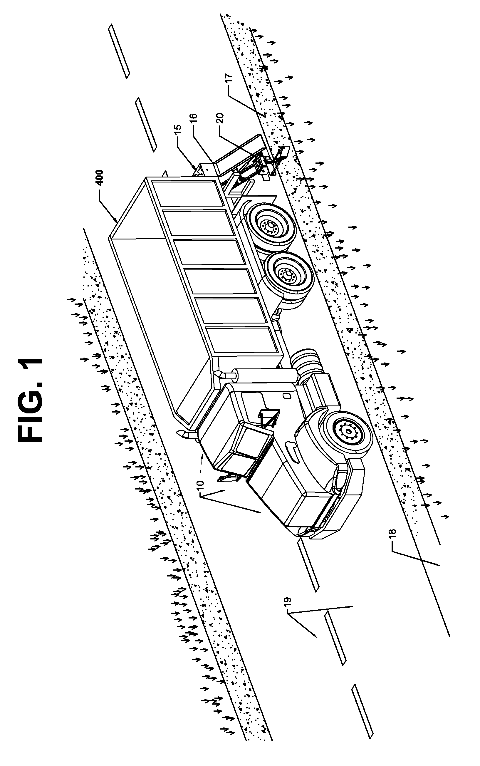
[0015]This apparatus allows for a one person operation for shoulder creation, maintenance and repair. For those communities with salting / sanding and snow plowing trucks, those same vehicles can be easily and quickly converted for shoulder placement, repair and maintenance as the salting and sanding dump trucks easily handle the aggregate as well. The end result being better roadway shoulders at less cost. It further provides for adjustable shoulder widths, adjustable shoulder heights, adjustable shoulder pitch, adjustable shoulder depth and allowance for the yaw and vertical rotation of the apparatus in relation to the roadway and truck while in operation.

Problems solved by technology

Over the course of time, existing shoulders are subject to wind, rain, snow plowing, drivers driving on the shoulder and other conditions that cause the shoulders to deteriorate such that the shoulder needs to be repaired.
The cost for purchasing graders and compactors can run into many hundred of thousands of dollars.
However, for most cities, townships and villages, those equipment purchasing costs cannot be justified as they only lay down and / or repair three (3) to five (5) miles of shoulder per year.
Neither of which are cost effective or easy to accomplish.
However, any new aggregate material must be laid by a separate piece of equipment and the leveling and compacting device is not adjustable in width.
As such, varying conditions, such as differing shoulder widths and mailboxes and roadway signs placed near the roadway cannot be accommodated.
Furthermore, while the '185 patent allows for straight vertical movement of the apparatus, there is no allowance for any pitch or width adjustment of the shoulder and no allowance for the yaw and vertical rotation of the apparatus relative to the truck when laying asphalt or aggregate.
U.S. Pat. No. 4,571,119 to Jones et al. and U.S. Pat. No. 6,089,785 to Bergman have identical problems in that they are not width nor pitch adjustable, nor do they accommodate for any yaw and vertical rotation of the apparatus.

Method used


Image

  • Adjustable method and apparatus for laying, leveling and compacting road shoulders
  • Adjustable method and apparatus for laying, leveling and compacting road shoulders
  • Adjustable method and apparatus for laying, leveling and compacting road shoulders

Examples


Embodiment Construction

[0041]Reference will now be made in detail to the description of the invention as illustrated in the drawings. Although the invention is described in connection with the drawings, there is no intent to limit the invention to the embodiment or embodiments disclosed therein. On the contrary, the intent is to include all alternatives, modifications, and equivalents included within the scope and spirit of the invention as defined by the appended claims. However, the invention and its alternatives, modifications, derivatives and / or equivalents in other applications are meant to be included within the scope and spirit of the invention as defined by the appended claims. For example, but without limitation, the invention has been described using channel, however, flat steel stock and / or angle iron can readily be substituted for channel. Similarly, the hitch bar could be solid or tubular and alternatives to the use of pivot pins, such as rotational sockets, and other means well known in the ...


PUM


Abstract

An apparatus for attachment to dump trucks having a dump bed and a chute for discharging material onto a road shoulder and / or roadway. The apparatus allows the truck with a single operator to perform shoulder and / or roadway surfacing and / or repair by receiving and grading repair material into place. The attachment being adjustable as to pitch, width and depth of the repair material. The attachment being adjustable to allow a greater or lesser amount of material to be applied to a shoulder closer to the roadway surface if a deeper fill is required. The apparatus allows for rotational movement between the apparatus and the dump truck in a direction parallel to the roadways length and perpendicular to the roadways surface. The tires of the dump truck being utilized to compact the repair material. The apparatus being stored in a vertical position when not in use.

Description

FIELD OF THE INVENTION[0001]The present invention pertains to an apparatus and method for laying, leveling and compacting road aggregate material and, more particularly, for providing an apparatus and method for adjusting the height, width and pitch of the shoulder as well as accommodating the pivotal movement of the yaw, or rotational movement, between the truck and apparatus perpendicular to the length of the road and for the vertical rotation of the truck and apparatus parallel to the length of the road.BACKGROUND OF THE INVENTION[0002]Most paved or concrete roadways in the U.S. are provided with shoulder regions consisting of granular aggregates such as gravel, sand, crushed rock, pebbles, crushed shells, crumbled waste rubber and other such materials or mixtures of materials as are readily available in local areas. After new roads are laid, or old roads refurbished, the road shoulders are laid down and compacted. Most often, this is accomplished using a dump truck to lay the ag...

Claims


Application Information

Patent Timeline
IPC IPC(8): E04G21/10
CPCE01C19/4873E01H1/003
Inventor SCHMIDT, MICHAEL A
Owner BONNELL INDS
Learn More