
Image recording apparatus

a technology of image recording and recording frame, which is applied in the direction of transportation and packaging, thin material processing, and article separation, etc., can solve the problems of easy distortion of the first body, and achieve the effect of maintaining the positional accuracy of each componen

Active Publication Date: 2012-10-30
SCOMI OILTOOLS CANADA +1
View PDF23 Cites 5 Cited by
  • Summary
  • Abstract
  • Description
  • Claims
  • Application Information

AI Technical Summary

Benefits of technology

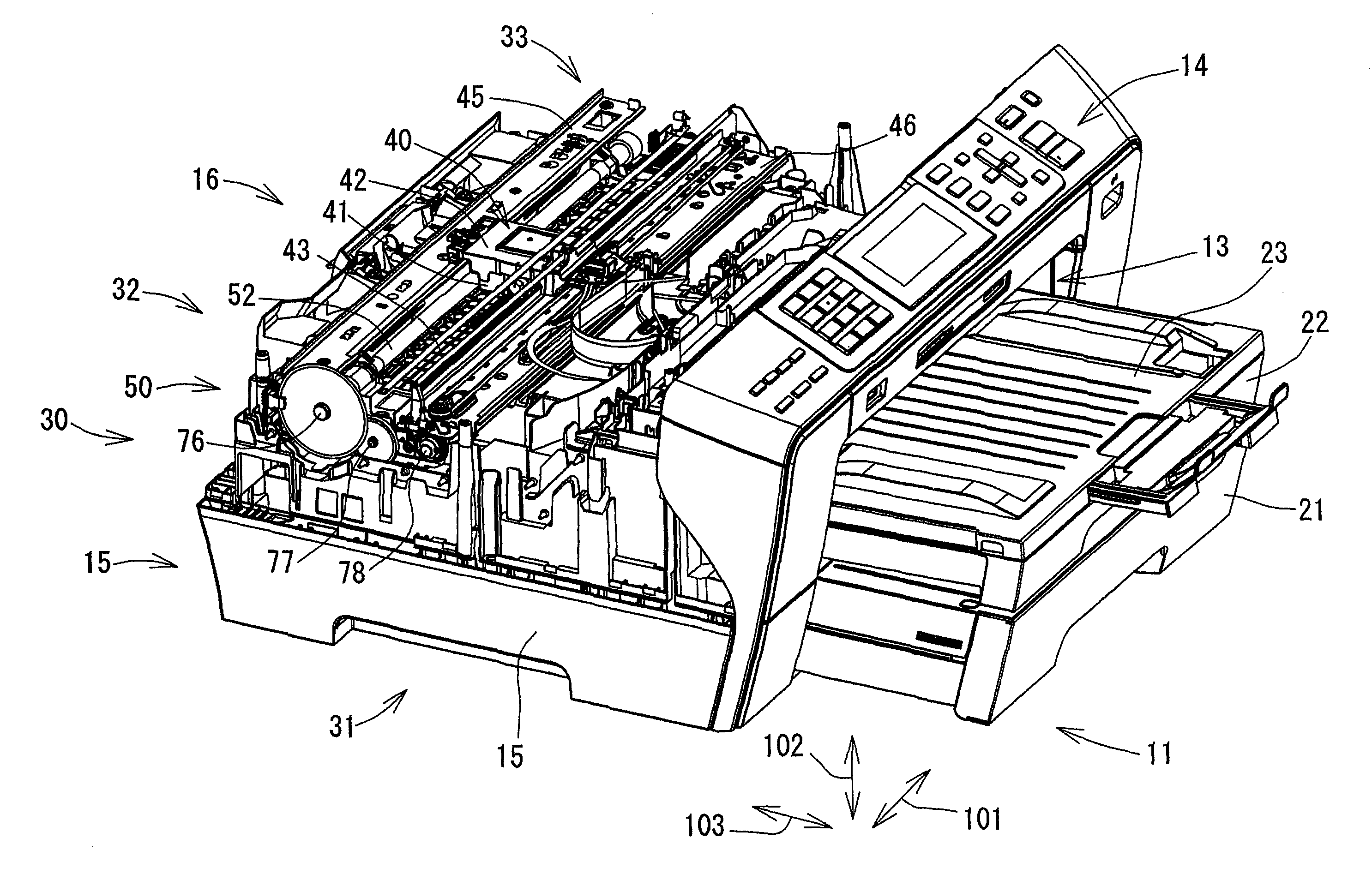
The present invention provides an image recording apparatus that can maintain positional accuracy of each component of the apparatus even without the first and second bodies being connected to each other. This is achieved by designing the apparatus with conveying devices and first and second bodies that can easily maintain their position even when connected or disconnected. The first and second bodies are connected by removable attachment, and the apparatus includes a frame member that holds the conveying device and helps maintain its position. The first and second bodies have first and second box portions that can accommodate sheet holders, and the first and second box portions are connected through a connector and a support portion on the bottom surface of the first box portion. The second body also has second foot portions that are in contact with the installed surface, and the weight of the second body is transmitted onto the installed surface through the support portion and the frame member, stabilizing the shape of the second box portions. This allows for stable positioning of the conveying device and other components of the apparatus, regardless of whether the first and second bodies are connected or not.

Problems solved by technology

Since the first space is provided between the pair of first box portions, the first body could easily suffer from distortion.

Method used


Image

  • Image recording apparatus
  • Image recording apparatus
  • Image recording apparatus

Examples


Embodiment Construction

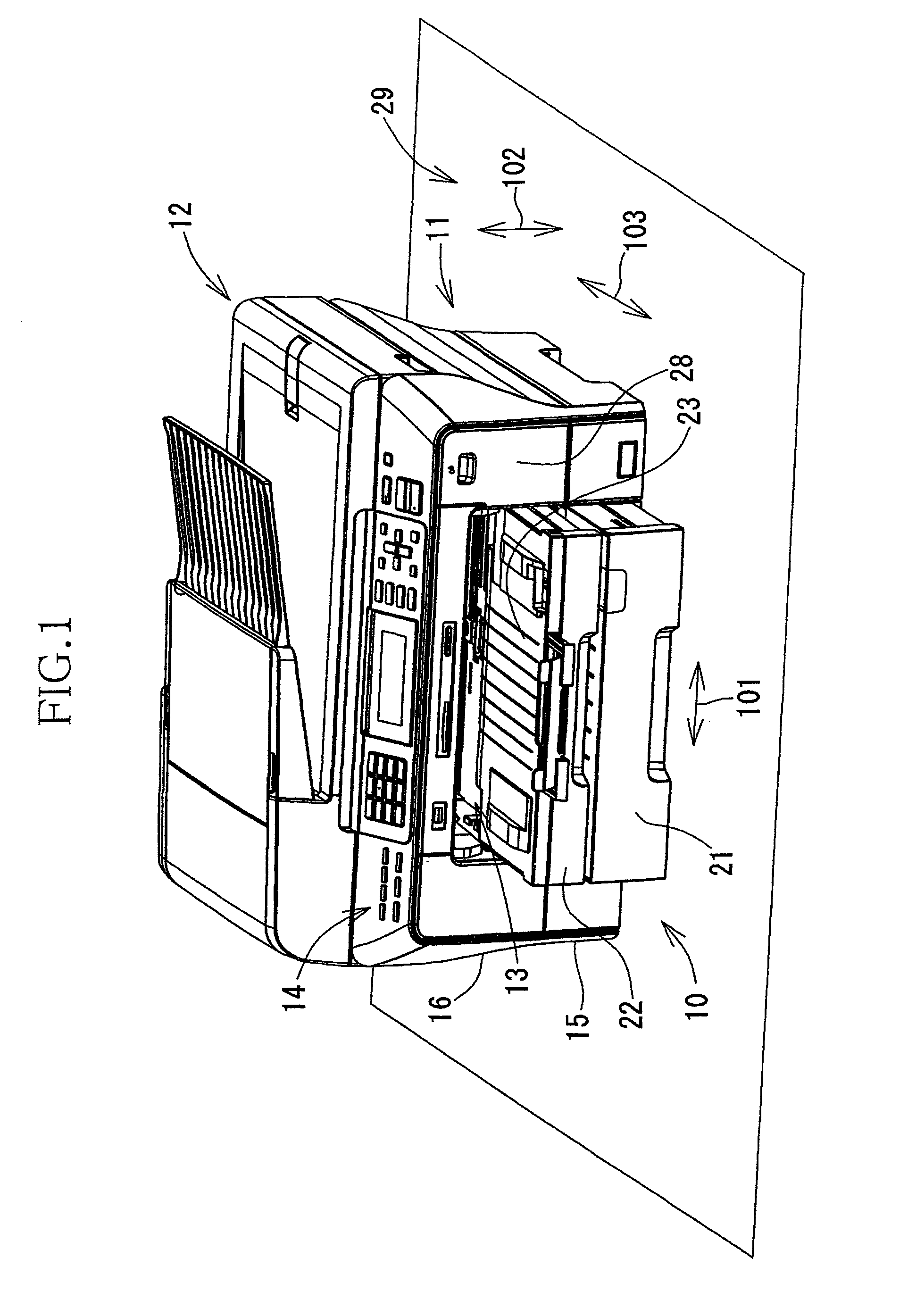
[0037]FIG. 1 shows an image recording apparatus in the form of a multifunction apparatus 10 that is constructed according to an embodiment of the invention. The multifunction apparatus 10 includes a printer 11 and a scanner 12 that are integral with each other, so as to have printer, scanner, copier and facsimile functions. The multifunction apparatus 10 is used while being installed on an installed surface 29 that is a horizontal and flat surface. It is noted that the image recording apparatus according to the invention does not necessarily have to be provided by the multifunction apparatus 10 including the scanner 12 in addition to the printer 11, but may be provided by a single function apparatus not having the scanner and facsimile functions.

[0038]As shown in FIG. 1, the multifunction apparatus 10 has a generally rectangular parallelepiped shape as a whole. Specifically, the apparatus 10 has width and depth dimensions as measured in width and depth directions 101, 103, respectiv...


PUM


Abstract

An image recording apparatus including first and second bodies that are removably connected to each other. The first body includes (i-a) a pair of first box portions (i-b) a connector interconnecting the first box portions, (i-c) at least one first foot portion provided on a bottom surface of each of the first box portions so as to be in contact with an installed surface, and (i-d) at least one first support portion extending upwardly from the at least one first foot portion. The second body includes (ii-a) a pair of second box portions, (ii-b) a connector interconnecting second box portions, and (ii-c) at least one second foot portion provided on a bottom surface of each of the second box portions. The second foot portion is located in a position aligned with the first support portion, so as to be in contact with a distal end of the first support portion. A sheet conveying device is held by a frame member which bridges between the second box portions.

Description

CROSS REFERENCE TO RELATED APPLICATION[0001]This application claims priority from Japanese Patent Application No. 2008-094081 filed on Mar. 31, 2008, the disclosure of which is herein incorporated by reference in its entirety.BACKGROUND OF THE INVENTION[0002]1. Field of the Invention[0003]The present invention relates to an image recording apparatus having first and second bodies that are removably connected to each other such that the second body is disposed on an upper side of the first body wherein the second body is provided with components configured to perform at least one common function that is common to a plurality of types of image recording apparatuses while the first body is provided with components configured to perform at least one additional function that is other than the above-described at least one common function.[0004]2. Discussion of Related Art[0005]In an image recording apparatus such as an inkjet printer, ink droplets are ejected from a recording head toward ...

Claims


Application Information

Patent Timeline
Patent Type & Authority Patents(United States)
IPC IPC(8): B65H3/44
CPCB65H1/266B65H2402/10B65H2402/40B65H2402/60B65H2405/332B65H2801/06
Inventor SAMOTO, KENJI
Owner SCOMI OILTOOLS CANADA
Learn More