
Magnetic clip assembly for manufacture of dynamoelectric machine

a technology of magnetized clip and dynamoelectric machine, which is applied in the direction of dynamo-electric machines, electrical apparatus, applying solid insulation, etc., can solve the problems of slot insulation being damaged, broken or frayed, and prone to problems such as affecting the operation of the machine, so as to achieve the effect of reducing or eliminating

Active Publication Date: 2012-10-23
GENERAL ELECTRIC CO
View PDF18 Cites 0 Cited by
  • Summary
  • Abstract
  • Description
  • Claims
  • Application Information

AI Technical Summary

Benefits of technology

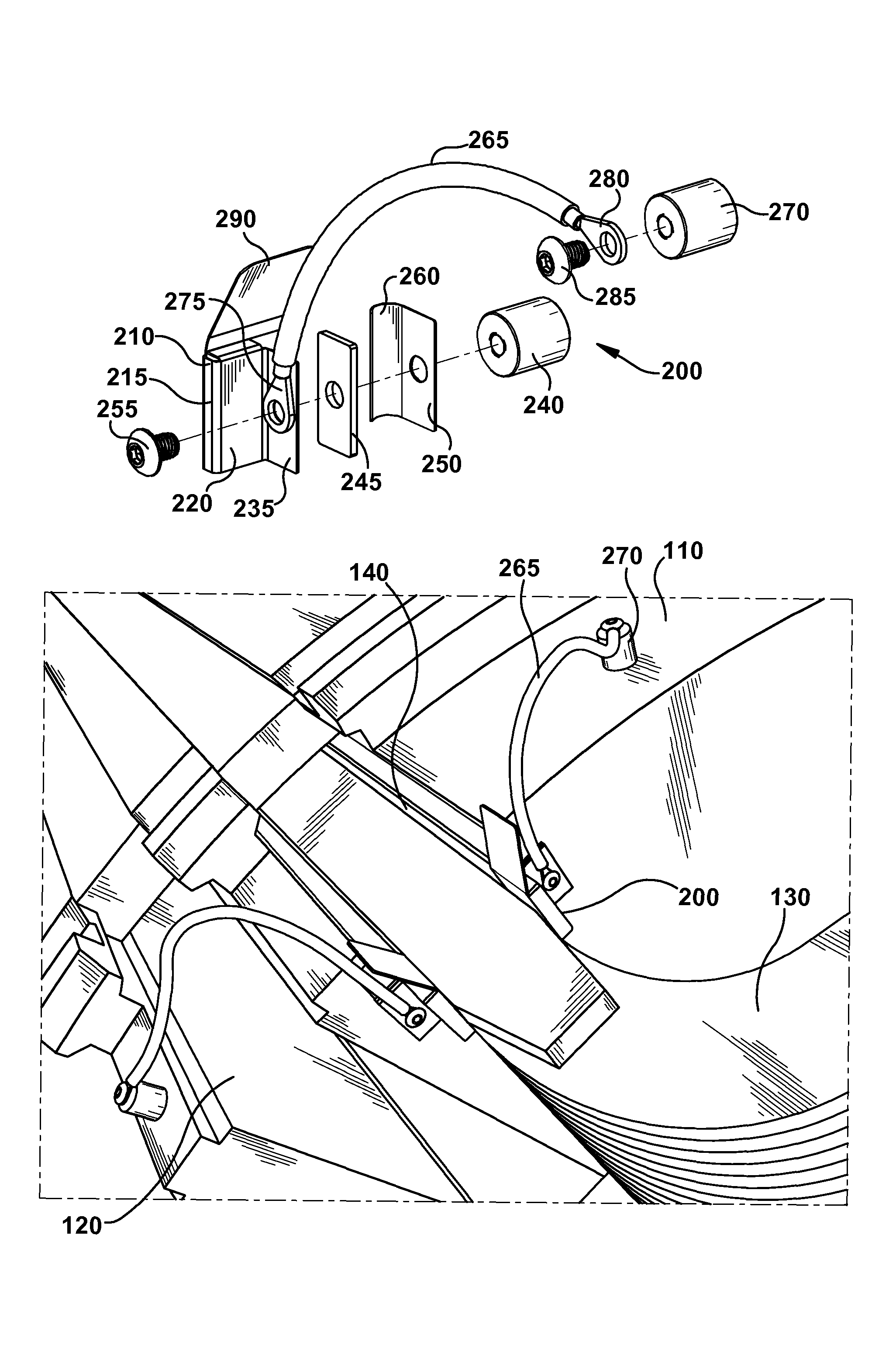
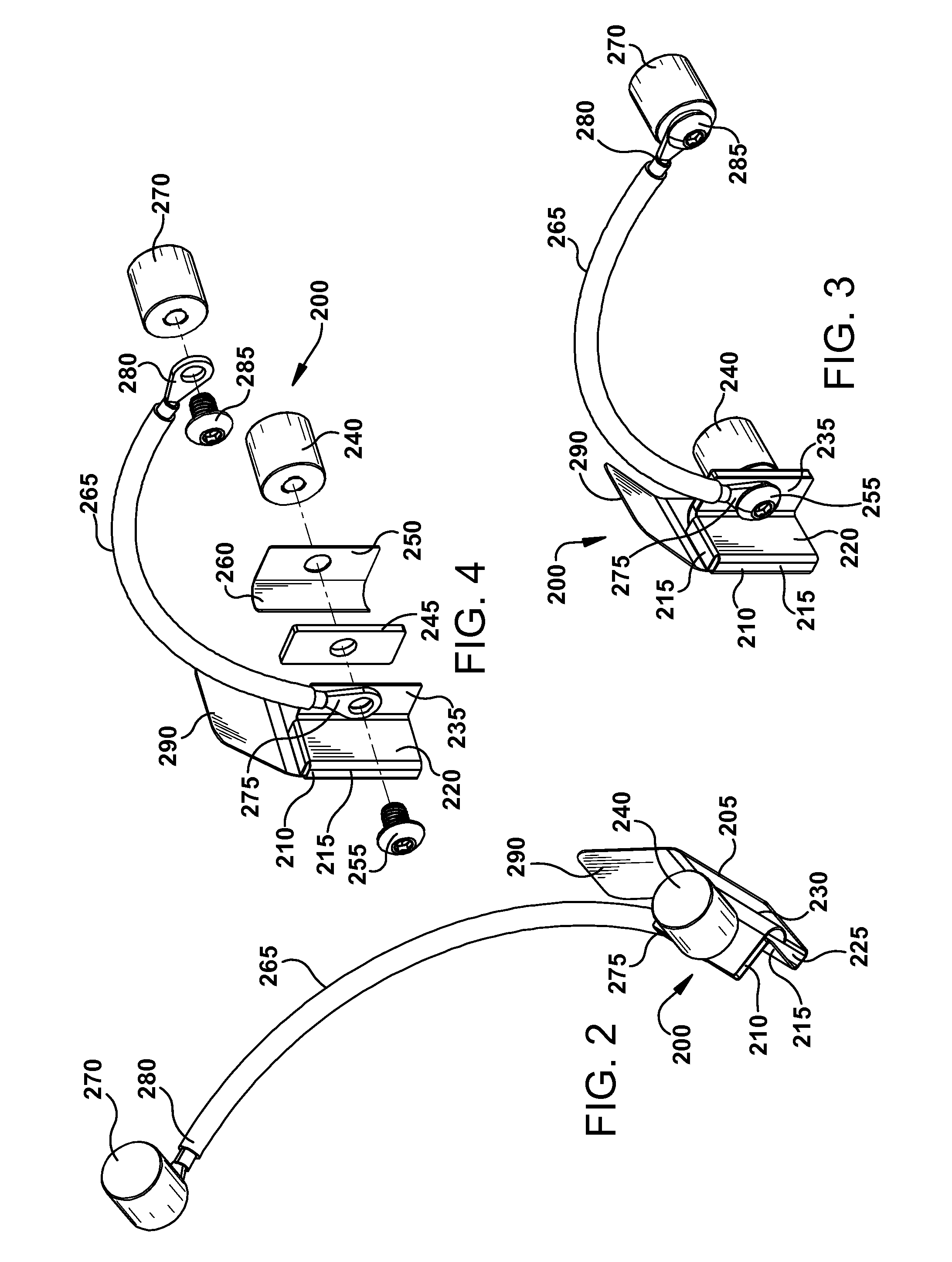
"The present invention provides a magnetic clip assembly for use in the manufacturing process of electric generators. The assembly is designed to securely hold and protect slot insulation during the winding process, minimizing damage to the insulation. The assembly includes a base, a receptacle with three side surfaces, a top surface, and an opening, a first tab on the top surface, a first magnet attached to the first tab, and a second magnet attached to the first tab at an opposing surface. The assembly is designed to securely hold and protect slot insulation within the slots of the rotor body, ensuring proper installation of field coil turns. The technical effects of the invention include improved efficiency and reliability of the winding process, reduced likelihood of damage to the insulation, and improved performance of the electric generator."

Problems solved by technology

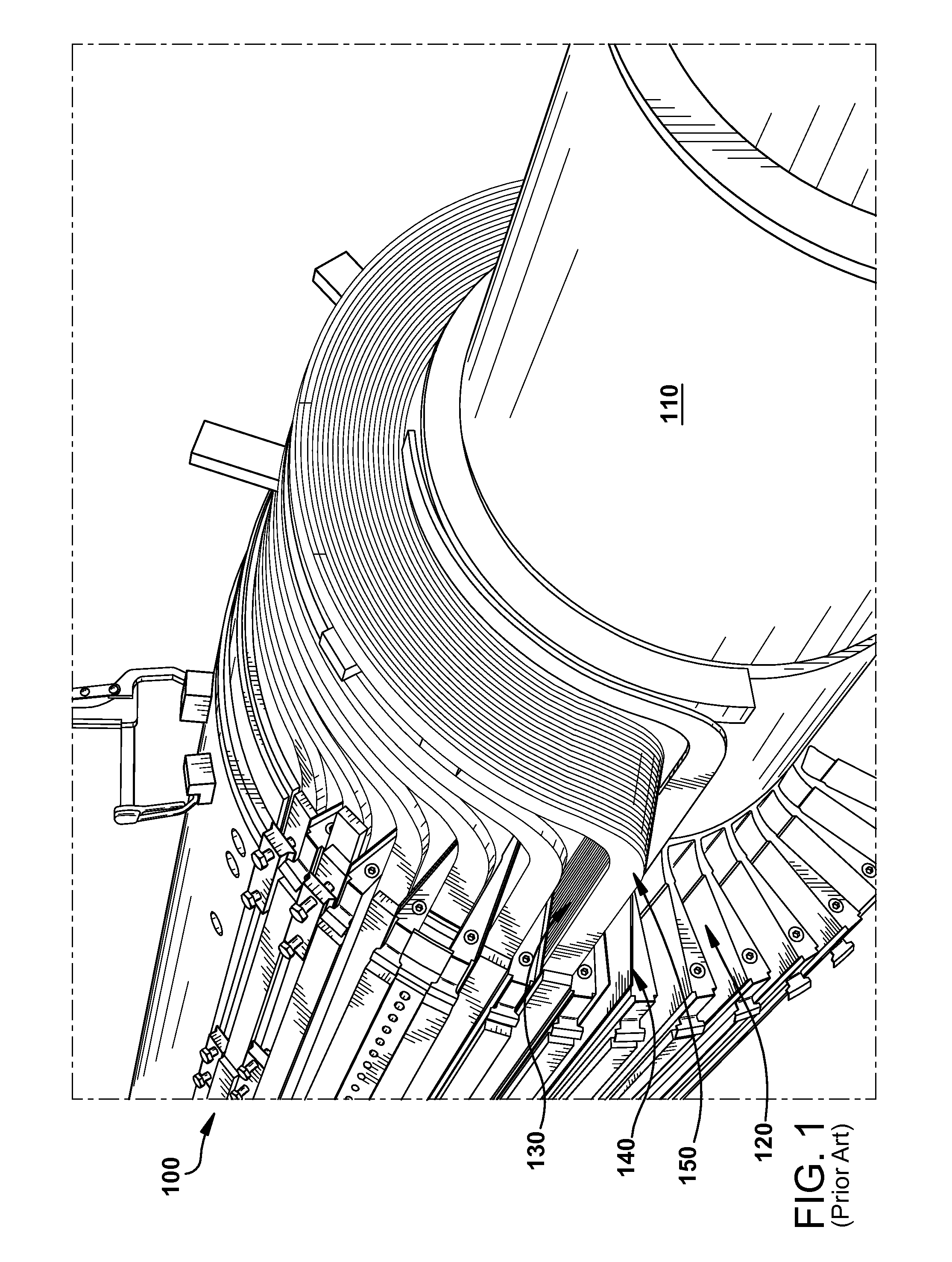
During the manufacturing of an electric generator, a problem can arise during the winding (assembly process) of the field coils (i.e., placement of the coil windings in the axial slots against the side surfaces of the slot insulation).
In particular, the slot insulation tends to become damaged (i.e., broken or frayed) as the turns of field coils are installed in the axial slots.
That is, the turns of field coils contact edges of the slot insulation during installation and sometimes break or fray the slot insulation, necessitating replacement of the insulation.
Because the ends of each installed field coil have to be brazed, the labor costs in unbrazing and removing the coils in order to replace damaged slot insulation can be, excessive especially if multiple turns of a coil have already been installed in the axial slots.
In addition to excessive labor costs, there are delays in manufacturing the electric generators when it becomes necessary to replace slot insulation.

Method used


Image

  • Magnetic clip assembly for manufacture of dynamoelectric machine
  • Magnetic clip assembly for manufacture of dynamoelectric machine
  • Magnetic clip assembly for manufacture of dynamoelectric machine

Examples


Embodiment Construction

[0012]Various embodiments of the present invention include using the magnetic clip assembly described herein to receive and secure slot insulation against the side surfaces of axial slots disposed in a rotor body of a dynamoelectric machine such as an electric generator, as a multitude of field coil turns are arranged in each of the slots. Technical effects of the various embodiments of the present invention include improving the manufacturing winding process of an electric generator by minimizing or eliminating the damage to the slot insulation. Other technical effects include minimizing or eliminating, in most cases, the damage caused by post winding slot insulation adjustments required due to the insulation shifting during the winding process.

[0013]Although the various embodiments of the present invention are directed to using the magnetic clip assembly described herein with a large electric generator configuration, embodiments of the present invention are suitable for use with s...


PUM


Abstract

A magnetic clip assembly for use in the manufacture of an electric generator is provided. In one aspect there is a magnetic clip assembly that includes a base; a receptacle formed on a portion of the base having three side surfaces, a top surface and an opening formed therein with a pinching area to receive and secure an inserted material of varying thickness; a first tab formed on the top surface of the receptacle extending away from the opening; a first magnet coupled to a surface of the first tab; and a second magnet coupled to the first tab at an opposing surface of the tab containing the first magnet.

Description

BACKGROUND OF THE INVENTION[0001]The present invention relates generally to magnetic clip devices and more particularly to a magnetic clip assembly for use in the manufacture of a dynamoelectric machine such as an electric generator.[0002]A typical electric generator includes a rotor mounted within a stator. The rotor is an electromagnet that includes a multiple of field coils having a plurality of turns (windings or layers) typically made of copper or aluminum. A body of the rotor, typically made of steel, includes a multiple of axial slots disposed therein. The plurality of turns of field coils are arranged within each of these axial slots. Each of the field coils is electrically and mechanically isolated from the axial slots by slot insulation known as slot armor. The slot insulation serves to position and protect the field coils from electrical contact with the rotor body. Specifically, the slot insulation isolates the sides of the field coils. The field coils produce a magnetic...

Claims


Application Information

Patent Timeline
Patent Type & Authority Patents(United States)
IPC IPC(8): B25B11/00
CPCH02K15/063B25B11/002H02K3/345H02K15/09H02K15/10
Inventor STERLE, JOHN THOMAS
Owner GENERAL ELECTRIC CO
Learn More