
Microcurrent device with a sensory cue

a microcurrent device and cue technology, applied in the field of microcurrent devices with sensory cues, can solve problems such as the disruption of effective treatment, and achieve the effect of disrupting effective treatmen

Active Publication Date: 2012-10-16
JOHNSON & JOHNSON CONSUMER COPANIES
View PDF19 Cites 7 Cited by
  • Summary
  • Abstract
  • Description
  • Claims
  • Application Information

AI Technical Summary

Benefits of technology

Provides users with continuous and uninterrupted feedback on device operation, ensuring effective treatment delivery and immediate notification of any disruptions, enhancing user experience and treatment efficacy.

Problems solved by technology

If contact is lost, a sensory cue can alert the user that effective treatment has been disrupted.

Method used


Image

  • Microcurrent device with a sensory cue
  • Microcurrent device with a sensory cue
  • Microcurrent device with a sensory cue

Examples


Embodiment Construction

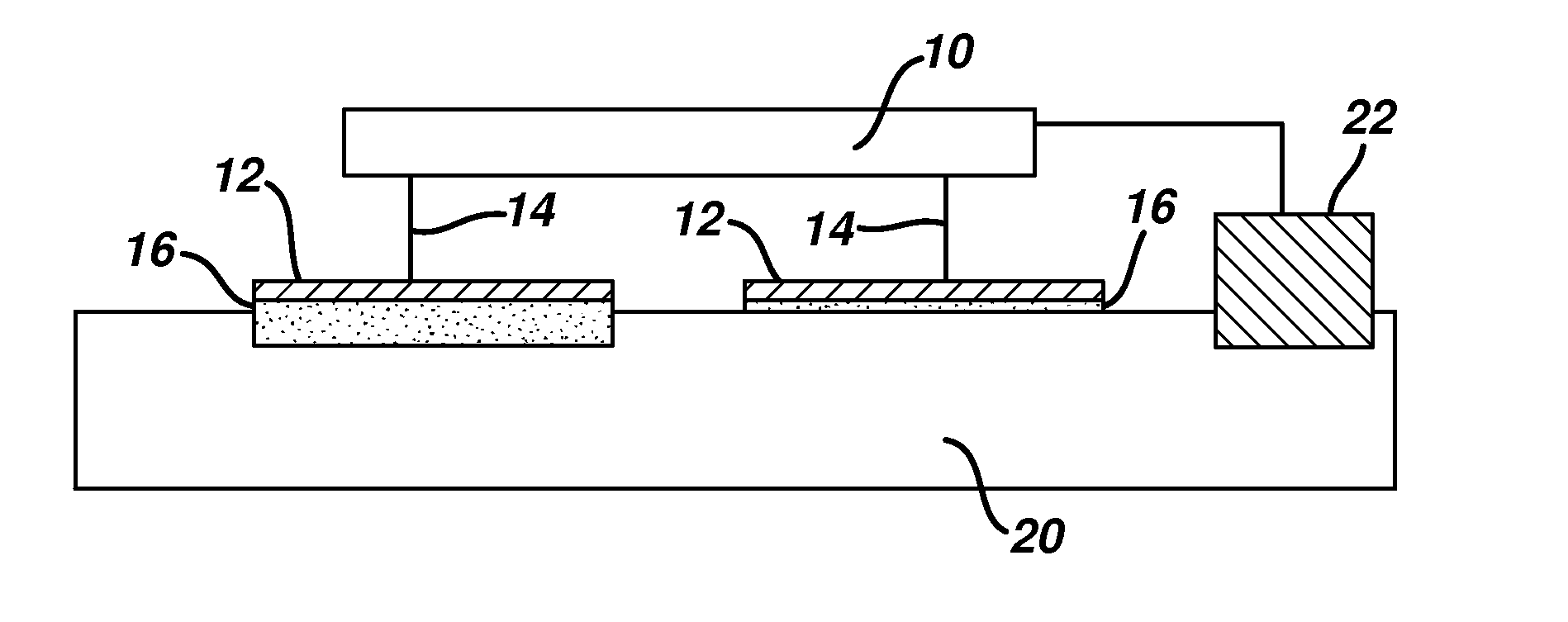
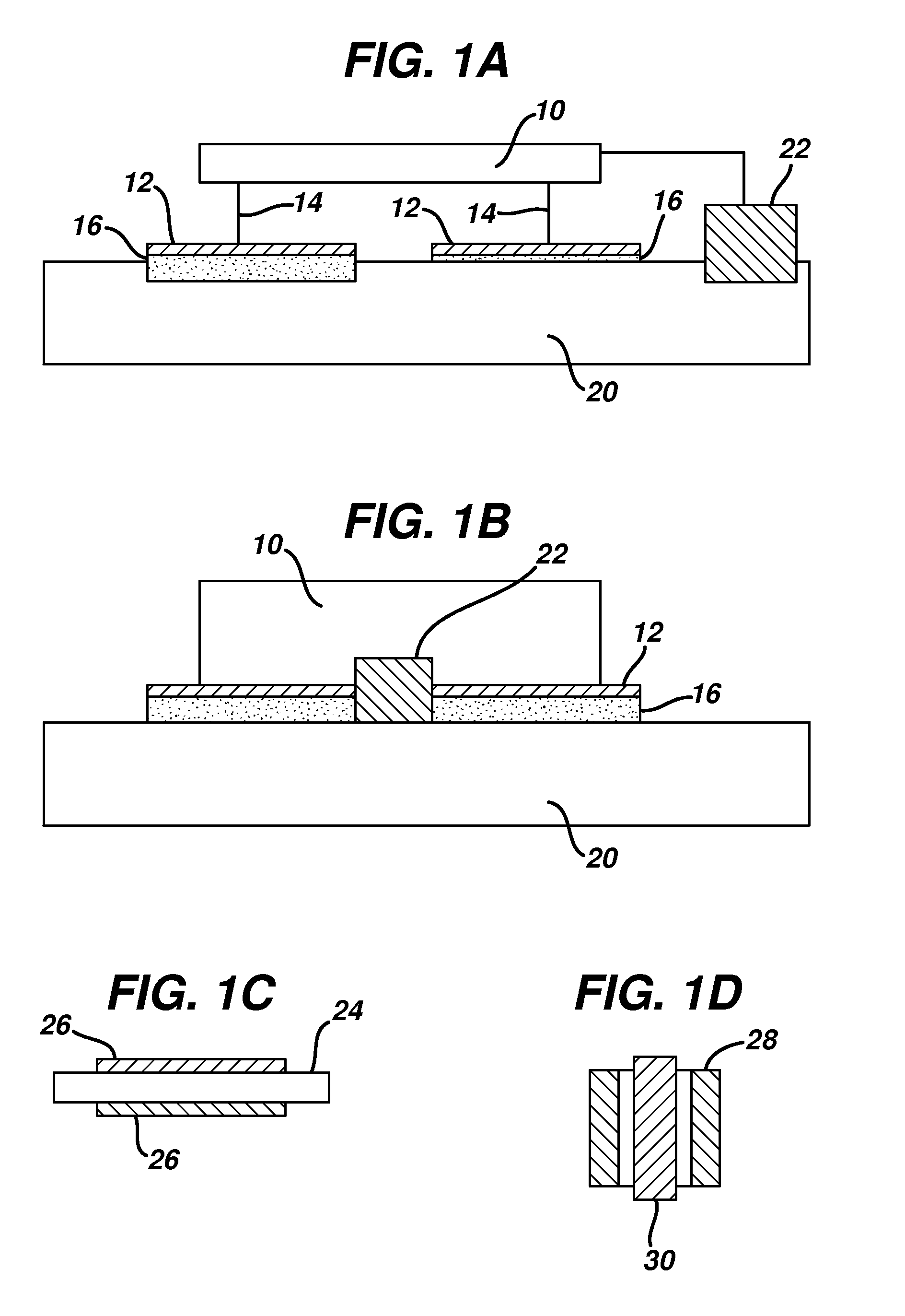
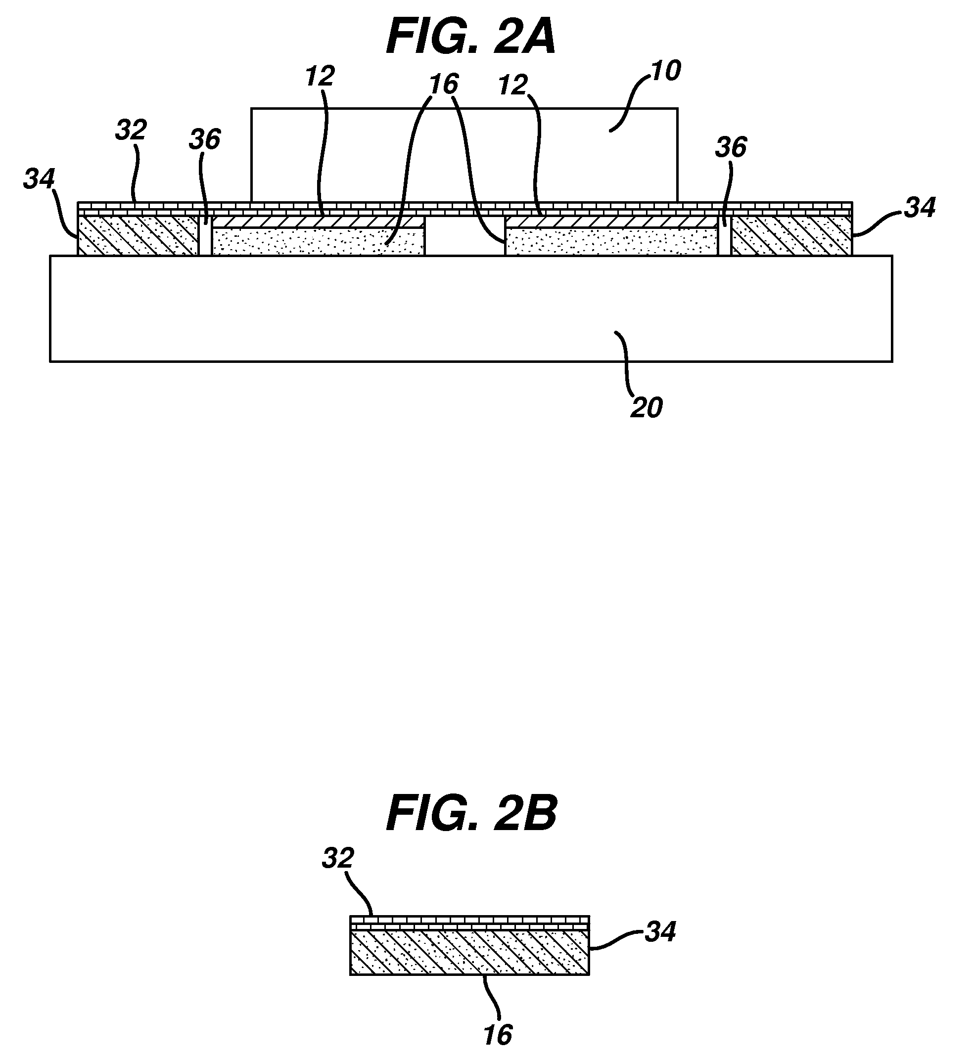
[0047]Microcurrent is an energy-based therapy, defined as the application of electrical current to the external parts of the body, typically on the skin, and applied as a current in a range of 20-500 microamperes. A conventional microcurrent apparatus is composed of a patch and a power supply source with positive and negative energy delivery electrodes leads attached from the power supply source. While microcurrent is applied to external parts such as the skin, it is used for treatment of pain in both muscle and joint tissue and may be applied in various configurations to the elbows, knees, back, shoulder or neck. Microcurrent therapy is differentiated from other electrotherapy devices in that the amount of current that is supplied is less than the amount used in transcutaneous electrical nerve stimulation (i.e. TENS).

[0048]FIGS. 1A and 1B illustrate wired and integrated wireless embodiments of electrostimulation devices or micro-current therapy devices of the present invention. A t...


PUM


Abstract

The present invention is directed to an apparatus that includes a microcurrent delivery device portion and at least one independent sensory cue delivery means. The independent sensory cue delivery means can provide an independent sensory cue selected from the group consisting of vibration, heat, cool, skin irritation, tingling, fragrance or auditory.

Description

CROSS REFERENCE TO RELATED APPLICATIONS[0001]This application claims priority of the benefits of the filing of U.S. Provisional Application Ser. No. 60 / 983,792, filed Oct. 30, 2007. The complete disclosures of the aforementioned related U.S. patent application is / are hereby incorporated herein by reference for all purposes.BACKGROUND OF THE INVENTION[0002]During the past decade, microcurrent therapy has been shown to be effective in pain control. Microcurrent electrical therapy or microcurrent therapy, first coined by Mercola and Kirsch in 1995, describes a new form of electro-medical intervention using biocompatible waveforms and uses current in the microampere range, 1000 times less than that of transcutaneous electrical nerve stimulation (i.e. TENS) and below the sensation threshold.[0003]Some of the early thinking relating to energy treatments, as shown in studies reviewed by North (9) and by Neumann (11), was that if some electricity is good perhaps more is better. This concept...

Claims


Application Information

Patent Timeline
Patent Type & Authority Patents(United States)
IPC IPC(8): A61N1/00A61B5/04A61H1/00
CPCA61N1/205A61N1/326A61N1/36021A61N1/36017A61N1/36071
Inventor KRIKSUNOV, LEO B.OMER, ALIYA Z.ROCHE, EDWARDGHAIM, JOSHUAFURGIUELE, NAOMI
Owner JOHNSON & JOHNSON CONSUMER COPANIES
Learn More