Display device, method for driving the same, and electronic device

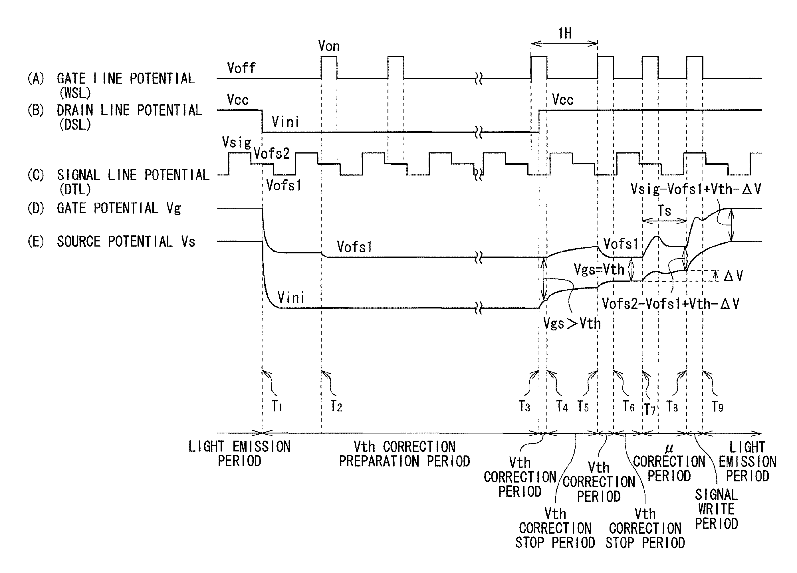
a technology of electronic devices and display devices, applied in the direction of static indicating devices, discharge tubes luminescnet screens, instruments, etc., can solve the problems of difficult to increase correction time ts, increase v, and shorten the correction time ts

Active Publication Date: 2012-10-16
JOLED INC
View PDF19 Cites 2 Cited by
  • Summary
  • Abstract
  • Description
  • Claims
  • Application Information

AI Technical Summary

Benefits of technology

[0027]In the display device, the method of driving the same, and the electronic device of the embodiment of the present invention, the potential difference between the gate and the source of the transistor is corrected to a threshold voltage of the transistor. After that, while the second drive unit outputs the third voltage, correction of mobility of the transistor is started. Subsequently, while the second drive unit outputs the second voltage, writing of a voltage according to the second voltage to the gate of the transistor starts. In such a manner, correction of mobility of the transistor and writing of the voltage according to the second voltage to the gate of the transistor (hereinbelow, simply referred to as writing to the gate) are performed separately. Therefore, time necessary to correct mobility of the transistor may be set freely. Since mobility of the transistor is corrected by using the third voltage having the predetermined magnitude, the mobility of the transistor may be corrected irrespective of the light emission luminance.
[0028]In the display device, the method of driving the same, and the electronic device of the embodiment of the present invention, the potential difference between the gate and the source of the transistor is corrected to a threshold voltage of the transistor. After that, while the second drive unit outputs the third voltage, correction of mobility of the transistor is started. Subsequently, while the second drive unit outputs the second voltage, writing of a voltage according to the second voltage to the gate of the transistor starts. Therefore, time necessary to correct mobility of the transistor may be set freely. Further, mobility of the transistor is corrected irrespective of the light emission luminance. Consequently, even in the case where the light emission luminance is low, μ correction may be made function reliably.

Problems solved by technology

Since the μ correction and the signal writing are performed simultaneously, the μ correction time Ts becomes inevitably short.
Therefore, it is difficult to increase the μ correction time Ts and increase ΔΔV.

Method used


Image

  • Display device, method for driving the same, and electronic device
  • Display device, method for driving the same, and electronic device
  • Display device, method for driving the same, and electronic device

Examples


application examples

MODULE AND APPLICATION EXAMPLES

[0084]Application examples of the display device 1 described in the foregoing embodiment will be described below. The display device 1 of the embodiment is applicable to a display device of an electronic device in all of fields for displaying a video signal input from the outside or a video signal generated internally as an image or a video image, such as a television device, a digital camera, a notebook-sized personal computer, a portable terminal device such as a cellular phone, a video camera, or the like.

Module

[0085]The display device 1 of the embodiment is assembled as, for example, a module as illustrated in FIG. 9, into various electronic devices such as application examples 1 to 5 which will be described later. The module is obtained by, for example, providing a region 210 exposed from a member (not illustrated) sealing the display unit 10 in one side of a substrate 2 and forming external connection terminals (not illustrated) by extending wiri...

application example 1

[0086]FIG. 10 illustrates the appearance of a television device to which the display device 1 of the embodiment is applied. The television device has, for example, a video display screen unit 300 including a front panel 310 and a filter glass 320. The video display screen unit 300 includes the display device 1 of the embodiment.

application example 2

[0087]FIGS. 11A and 11B illustrate the appearance of a digital camera to which the display device 1 of the embodiment is applied. The digital camera has, for example, a light emitting unit 410 for flash, a display unit 420, a menu switch 430, and a shutter button 440. The display unit 420 includes the display device 1 of the embodiment.


PUM


Abstract

The present invention provides a display device, a method for driving the same, and an electronic device capable of making μ correction function reliably even in the case where light emission luminance is low. A potential difference between the gate and the source of a transistor is corrected to a threshold voltage of the transistor. After that, while a horizontal drive circuit outputs a third voltage Vofs2, correction of mobility of the transistor starts. Subsequently, while the horizontal drive circuit outputs a second voltage Vsig, writing of a voltage according to the second voltage Vsig to the gate of the transistor is started.

Description

BACKGROUND OF THE INVENTION[0001]1. Field of the Invention[0002]The present invention relates to a display device including a display unit having a light emitting element and a pixel circuit for each of pixels, and a drive unit driving the pixel circuit, and to a method for driving the same. The present invention also relates to an electronic device having the display device.[0003]2. Description of the Related Art[0004]In recent years, in the field of a display device for displaying an image, a display device using, as a light emitting element of a pixel, an optical element of a current driving type whose light emission luminance changes according to the value of a flowing current, for example, an organic EL (Electro Luminance) element is developed and is being commercialized.[0005]An organic EL element is a spontaneous light emitting element different from a liquid crystal element or the like. Consequently, in a display device using an organic EL element (organic EL display device)...

Claims


Application Information

Patent Timeline
Patent Type & Authority Patents(United States)
IPC IPC(8): G09G3/30
CPCG09G3/3233G09G2300/0819G09G2320/043G09G2300/0866G09G2300/0842
Inventor ARAKI, SHOJI
Owner JOLED INC
Why Eureka
Try Eureka