Direct expansion evaporator

a technology of evaporator and evaporator body, which is applied in the direction of indirect heat exchangers, domestic cooling devices, lighting and heating devices, etc., can solve the problems of inefficiency of heat transfer, limited contact area between copper tubes and feeding tubes, and complicated fabrication procedures, etc., and achieves the effect of more efficien

Active Publication Date: 2012-09-25
DONG LINGYU
View PDF20 Cites 4 Cited by
  • Summary
  • Abstract
  • Description
  • Claims
  • Application Information

AI Technical Summary

Benefits of technology

[0014]An object of the present invention is to provide a direct expansion evaporator, which is able to be relatively more efficient for the heat exchanging process of making frozen product from raw material.
[0016]Another object of the present invention is to provide a direct expansion evaporator, wherein the two heat-exchange stages are a pre-cooling stage for initially pre-cooling the raw material at the entrance and a freezing stage for conclusively making the frozen product before the exit, so as to efficiently transferring thermal energy to make the frozen product.
[0017]Another object of the present invention is to provide a direct expansion evaporator, which is able to completely evaporate a refrigerant from liquid to gaseous phase, so as to prevent the back flow of the liquid refrigerant.
[0020]Another object of the present invention is to provide a direct expansion evaporator, wherein the traveling time of the refrigerant is prolonged at the pre-cooling stage to ensure the liquid refrigerant being completely evaporated.
[0021]Another object of the present invention is to provide a direct expansion evaporator, which is relatively simple in structure and high efficient in converting chemical energy to thermal energy for heat exchanging process of making frozen product, so as to minimize the manufacturing cost of the direct expansion evaporator of the present invention for incorporating with the refrigeration system.
[0025]a refrigerant passing through the heat exchange channel for heat exchanging with the raw material within the feeding channel, wherein when the refrigerant flows at the pre-cooling portion of the heat exchange channel, the raw material fed from the feeding end of the feeding channel is initially pre-cooled at a pre-cooling temperature, and when the refrigerant flows at the freezing portion of the heat exchange channel, the raw material is then substantially frozen to form the frozen product before the frozen product is dispensed at the dispensing end of the feeding channel while being energy efficient.

Problems solved by technology

However, the contacting area between the copper tube and the feeding tube is limited.
The heat is conductively transferred through two layers, the walls of copper tube and feeding tube, so that the heat transferring is inefficient.
Although it has higher heat transfer rate to perform a relatively more efficient heat exchanging, it is complicated in fabrication procedure.
Thus, it also results in high manufacturing cost and low productivity.
Thus, it is high in manufacturing cost and not suitable for batch process or mass production.
The ice cream raw material made in the traditional spiral type can not efficiently provide the thermal energy that needed for freezing the ice cream to a desired hardness.
The spiral type does not have enough expansion area in the heat exchange channel for release the thermal energy in the expanded evaporation manner.
Thus, the spiral type of direct expansion evaporator uses relatively more power and is not efficient for using in batch process for producing a massive amount of frozen product.
For another example, frozen yogurt needs more thermal energy to form the final frozen product, otherwise, it usually tempts to be too soggy or liquefied to become the frozen yogurt.
The existing heat exchangers of direct expansion evaporator can not provide an efficient and capable of producing a relatively larger amount of frozen products.

Method used


Image

  • Direct expansion evaporator
  • Direct expansion evaporator
  • Direct expansion evaporator

Examples


Embodiment Construction

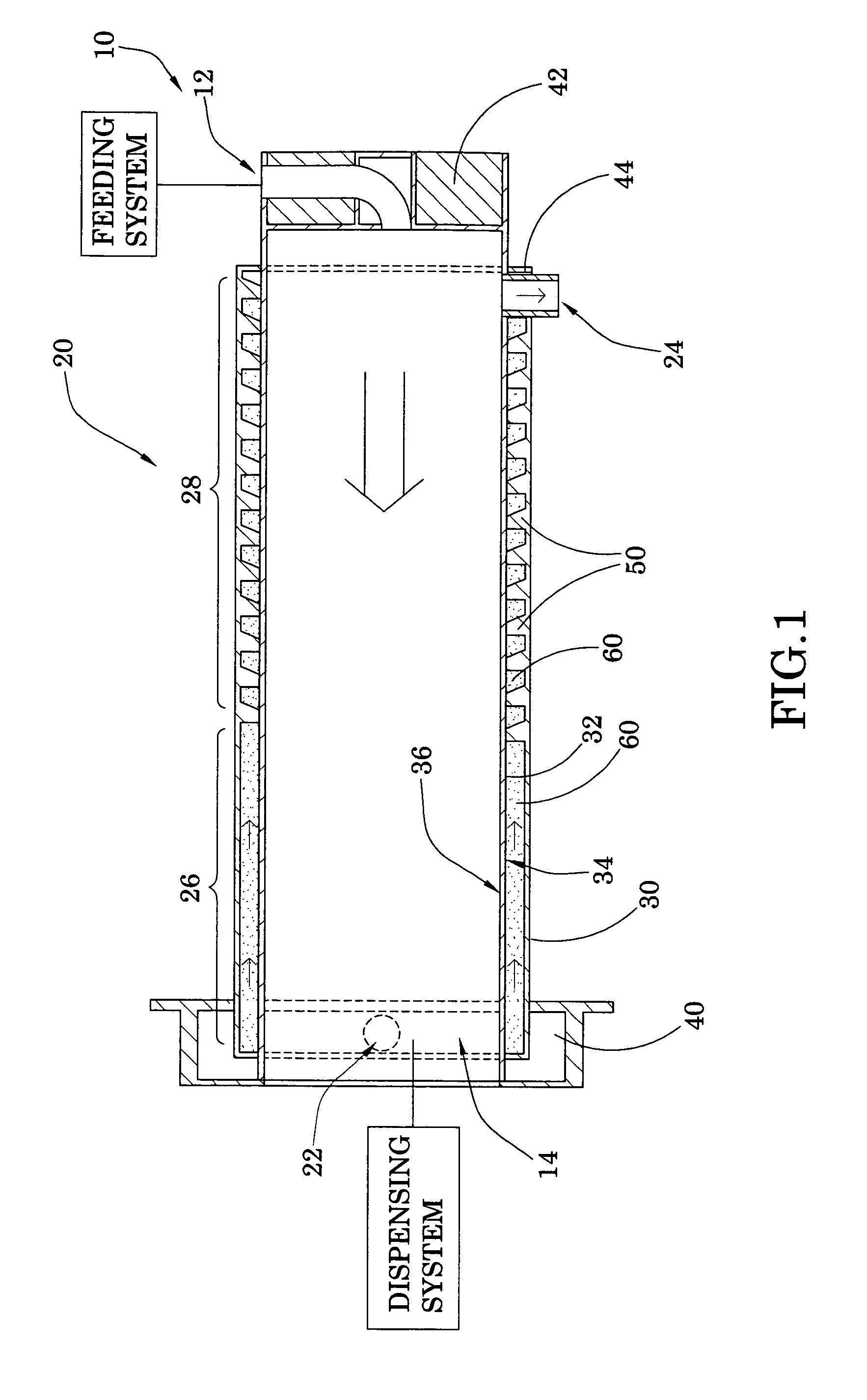
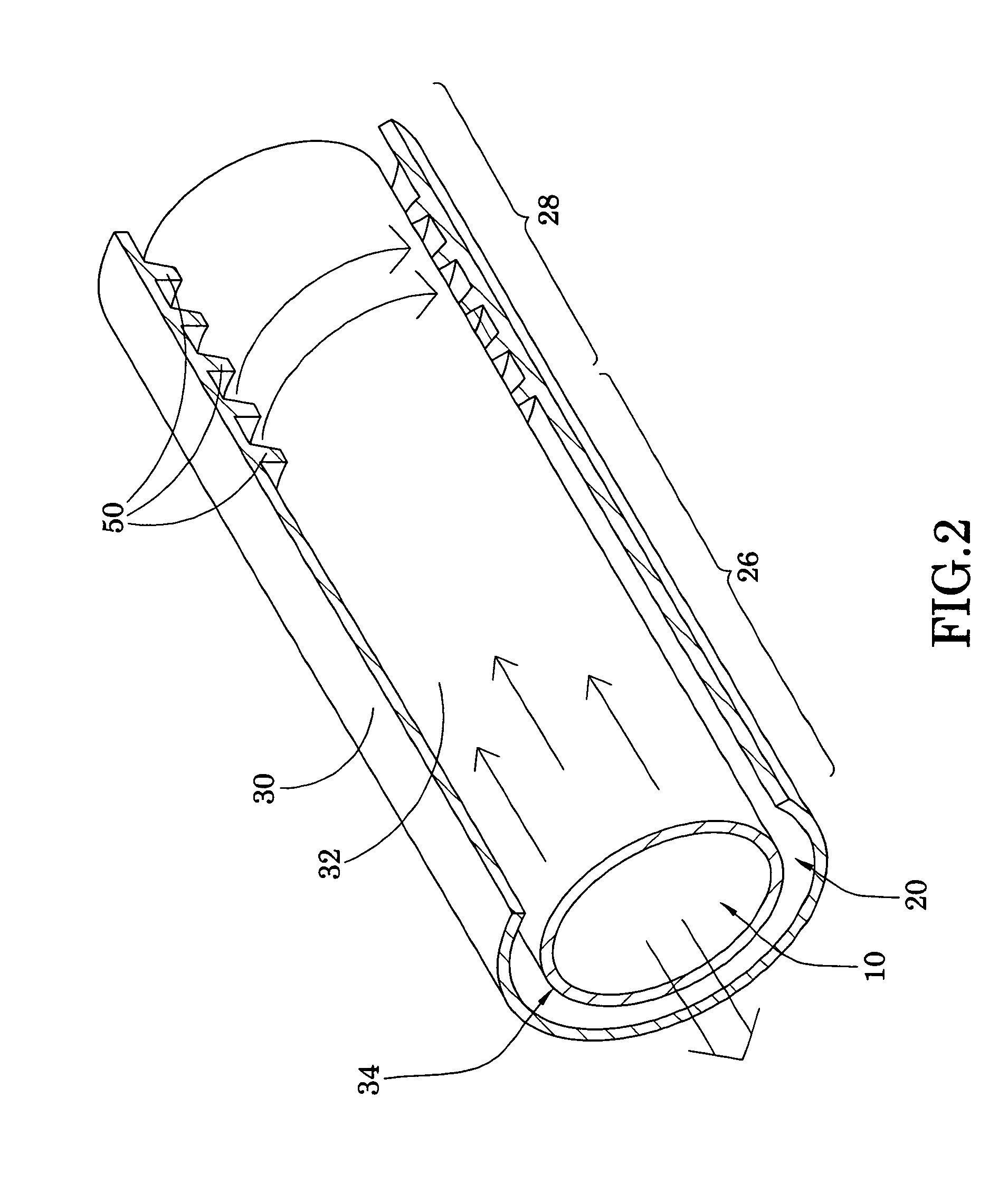
[0030]Referring to FIGS. 1 and 2 of the drawings, a direct expansion evaporator according to a preferred embodiment of the present invention is illustrated, wherein the direct expansion evaporator is adapted for heat-exchanging with a heat source. According to the preferred embodiment, the direct expansion evaporator is incorporated with a refrigeration system for making a frozen product from a raw material. For example, a heat exchanger of the direct expansion evaporator is provided to supply a thermal energy for exchanging heat between a refrigerant 60 and the raw material, so as to make the frozen product.

[0031]The direct expansion evaporator comprises a feeding channel 10 and a heat exchange channel 20 thermally communicating with the feeding channel 10 for heat exchanging.

[0032]The feeding channel 10 has a feeding end 12 and an opposite dispensing end 14 for the raw material feeding through the feeding channel 10 from the feeding end 12 to the dispensing end 14.

[0033]The heat e...


PUM


Abstract

A direct expansion evaporator for making a frozen product from raw material includes a feeding channel, a heat exchange channel thermally communicating with the feeding channel, and a refrigerant flowing within the heat exchange channel for exchanging heat between the raw material within the feeding channel and the refrigerant within the heat exchange channel in an expanded evaporation manner. Therefore, the refrigerant releases the thermal energy via the phase changing from liquid to gaseous state of the refrigerant. The heat exchange channel has a pre-cooling portion for pre-cooling the raw material at a predetermined temperature and a freezing portion for freezing the raw material to a final predetermined temperature of the frozen product in two-stage evaporation manner. Thus, the direction expansion evaporator provides a relatively more efficient way for making the frozen product, so as to increase the quality of the frozen product.

Description

BACKGROUND OF THE PRESENT INVENTION[0001]1. Field of Invention[0002]The present invention generally relates to a heat exchange apparatus, and more particularly to a direct expansion evaporator for a refrigeration system, wherein the direct expansion evaporator provides two heat-exchange stages for making a frozen product from raw material while being energy efficient.[0003]2. Description of Related Arts[0004]A direct expansion evaporator for heat exchanging, such as a heat exchanger, is commonly and widely applied in lots of areas, such as industrial or medical application. For example, the heat exchanger is used in a chemical factory for cooling down a waste to prevent overheating the waste. Heat exchange is also applied in refrigeration, freezer system, or air conditioner for exchanging the heat from the air or the frozen product to keep it under certain temperature.[0005]Most of the heat exchange used for cooling system applies a refrigerant to provide a lower temperature source,...

Claims


Application Information

Patent Timeline
Patent Type & Authority Patents(United States)
IPC IPC(8): A23G9/00
CPCF25B39/02F28D7/026F28D7/106F28F13/06A23G9/14F25C1/12F28D2021/0071F28F2270/00
Inventor DONG, LINGYU
Owner DONG LINGYU
Why Eureka
Try Eureka