
High data rate electrical connector and cable assembly

a high data rate, electrical connector technology, applied in the direction of coupling device details, contact member manufacturing, coupling device connection, etc., can solve the problems of unsymmetrical ground relationship and difficulty in fitting 24 awg cables, and achieve the effect of reducing crosstalk, minimizing crosstalk, and convenient manufacturing

Inactive Publication Date: 2012-09-18
PANDUIT
View PDF40 Cites 41 Cited by
  • Summary
  • Abstract
  • Description
  • Claims
  • Application Information

AI Technical Summary

Benefits of technology

The invention is an electrical connector that reduces crosstalk in a high data connector / cable assembly. It can accommodate a range of twin-ax wire sizes and is easy to manufacture and reliable in use. The connector includes a circuit board with differential pair conductive traces and drain wire termination devices with separators between them. The drain wires are placed symmetrically with respect to their corresponding differential conductive pair. The technical effects of the invention are reduced crosstalk and improved signal quality in the connector.

Problems solved by technology

Some problems that arise from this termination method include that the drain wire is attached to the PCB next to only one of its differential pair signal conductors which creates an unsymmetrical relationship between the ground (drain wire) and its differential pair signal conductors.
The form factor for the QSFP connector is set by the SFF-8436 standard, and one challenge with respect to fitting the cable into the connector is that it can be difficult to fit 24 AWG cable, which is used for the longer reach cable assemblies.

Method used


Image

  • High data rate electrical connector and cable assembly
  • High data rate electrical connector and cable assembly
  • High data rate electrical connector and cable assembly

Examples


Embodiment Construction

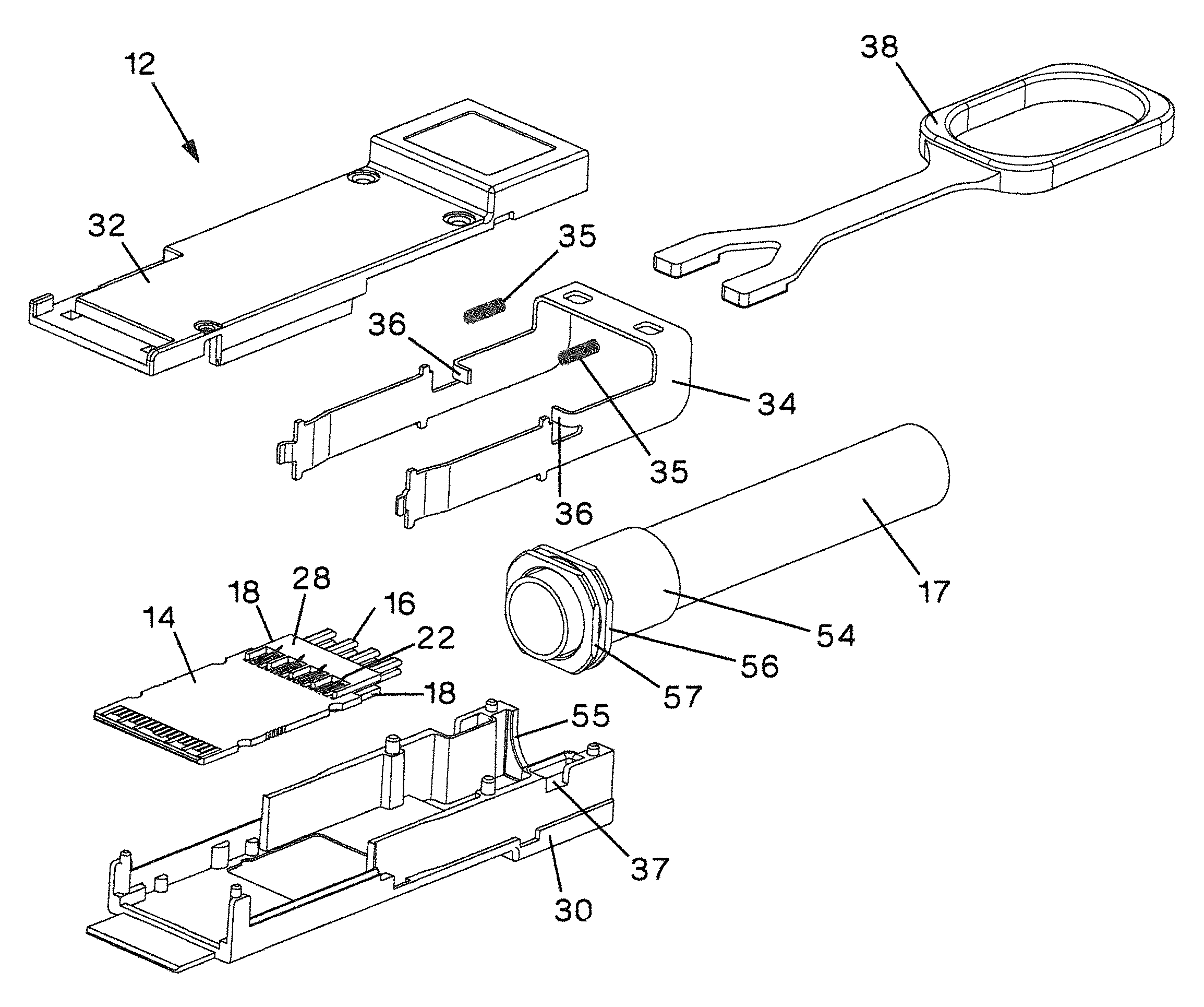
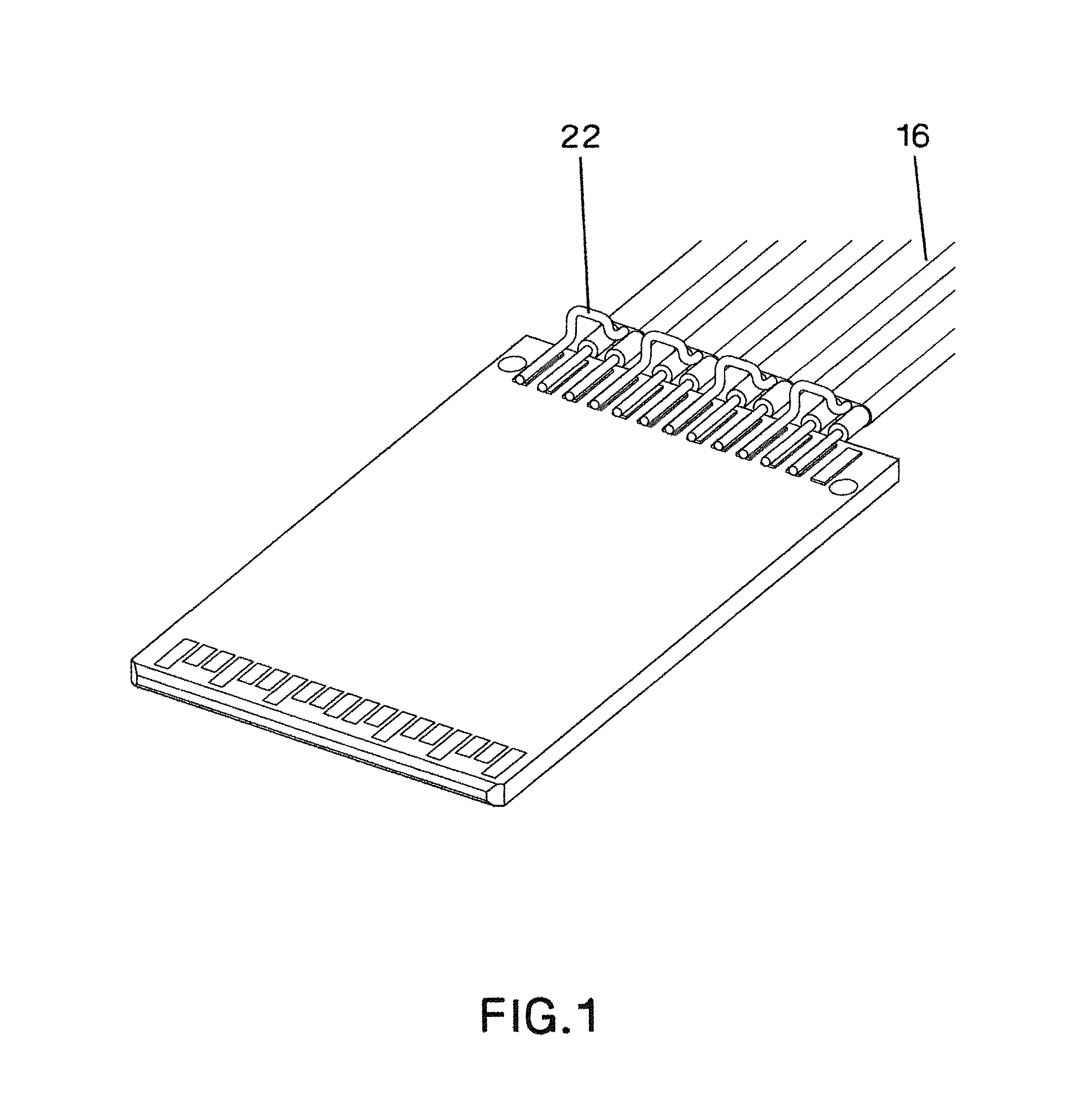
[0039]Embodiments of the present invention include an improved high data rate connector and cable assembly, and a method of minimizing the crosstalk therein. It was discovered that the NEXT crosstalk issues of the prior art primarily arise because of the way the twin-ax cable is terminated in the prior art (see FIG. 1, for example), where the drain wire is bent around the signal conductors and soldered to the PCB on one side of the signal conductors.

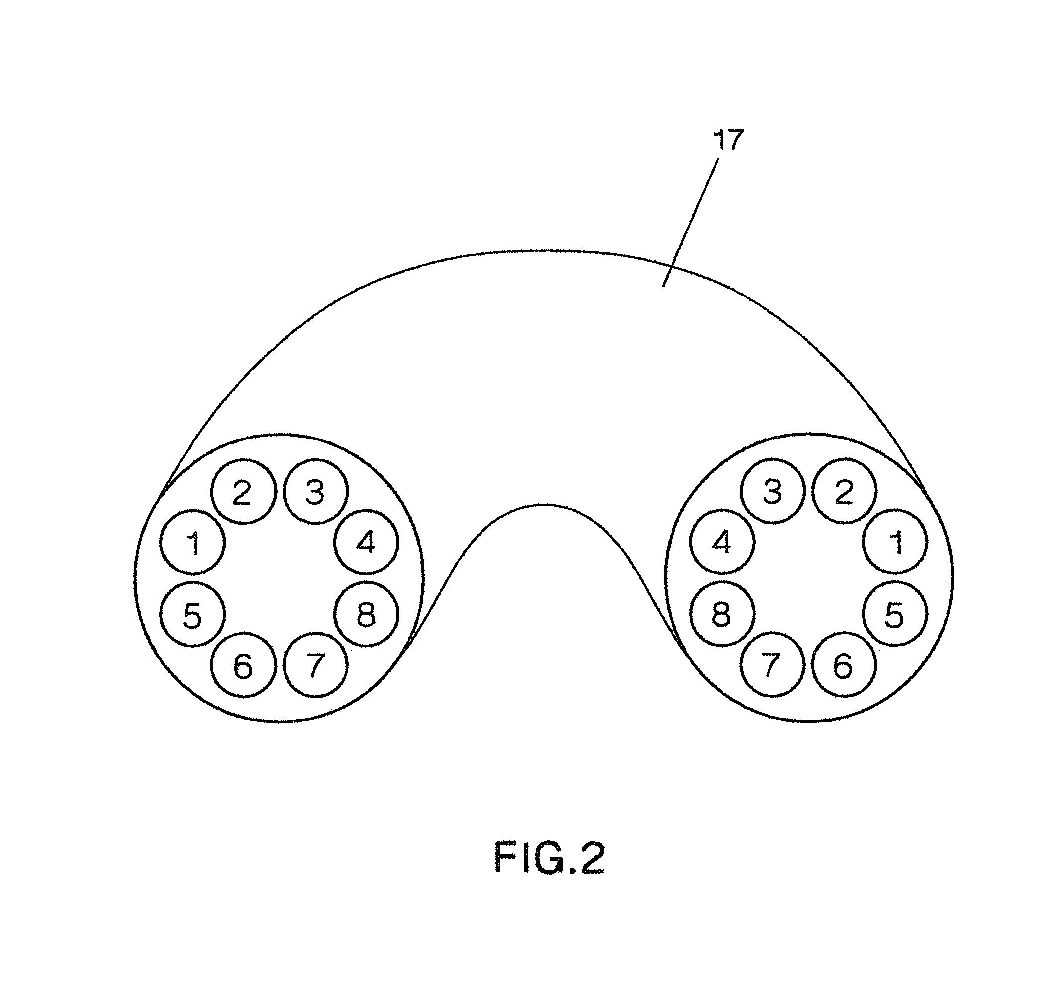
[0040]In some embodiments of the present invention, two ends of an eight-channel (eight sub-cables each having differential pair conductors and a respective drain wire) twin-ax cable typically present mirror images of the sub-cables as shown in FIG. 2. Although the connectors at either end of the cable assembly have essentially the same outward appearance and can fulfill the form factor requirements of the SFF-8436 standard created by the InfiniBand Trade Association, they have two different PCBs at either end of the cable assembly in or...


PUM

PropertyMeasurementUnit
sizeaaaaaaaaaa
lengthaaaaaaaaaa
dielectric constantaaaaaaaaaa

Abstract

An electrical connector has a first shell, an opposing second shell and a circuit board between the first shell and the second shell. The circuit board has a first side and an opposing second side and includes a plurality of differential pair conductive traces on each side. A first drain wire termination device is provided on the first side and includes at least one separator between at least one of the differential pair conductive traces on the first side and another of the differential pair conductive traces on the first side. A second drain wire termination device is connected to the second side and includes at least one separator between at least one of the differential pair conductive traces on the second side and another of the differential pair conductive traces on the second side.

Description

BACKGROUND OF THE INVENTION[0001]1. Field of the Invention[0002]The present invention relates to a high data rate electrical connector and cable assembly and, more particularly, to a connector / cable assembly which includes a connector or connectors attached to a cable having multiple twin-ax wire pairs.[0003]2. Description of the Related Art[0004]The Quad Small Form-Factor Pluggable (QSFP) connector is a connector capable of achieving a 40 Gb / s data rate (QDR, quad data rate, with the governing standards specifying a bandwidth of approximately 5 GHz) using InfiniBand, Ethernet, or other networking protocols. To achieve these high data rates, particularly with respect to 40 Gb / s Ethernet, crosstalk between the differential pairs within the connector must be reduced. Reducing crosstalk allows for a higher signal-to-noise ratio and reduces the amount of processing needed to achieve these higher data rates.[0005]A QSFP cable assembly is a twin-ax cable with a QSFP connector module attac...

Claims


Application Information

Patent Timeline
Patent Type & Authority Patents(United States)
CPCH01R13/6471H01R13/6658H01R13/6593H01R9/034Y10T29/49204H01R12/596H01R13/65914
Inventor STRAKA, FRANK M.MARTINO, NICHOLAS G.PATEL, SATISH I.SEPIC, GINA L.
Owner PANDUIT
Learn More