O3 production apparatus and exhaust gas purification system for internal combustion engine

a technology of exhaust gas purification system and production apparatus, which is applied in mechanical equipment, machines/engines, separation processes, etc., can solve the problems of unlikely deterioration of fuel economy and fuel economy deterioration, and achieve the effect of promoting pm oxidation and promoting the removal of pm from the filter

Inactive Publication Date: 2012-09-18
TOYOTA JIDOSHA KK
View PDF18 Cites 1 Cited by
  • Summary
  • Abstract
  • Description
  • Claims
  • Application Information

AI Technical Summary

Benefits of technology

[0008]An object of the present invention is to provide a technology that enables production of O3 to be supplied to the exhaust gas of an internal combustion engine while suppressing deterioration of the fuel economy.
[0010]When the operation state of the internal combustion engine is a decelerating operation state, deterioration of the fuel economy is unlikely to occur even if electric power is consumed. Therefore, according to the present invention, it is possible to produce O3 to be supplied to the exhaust gas of the internal combustion engine while suppressing deterioration of the fuel economy.
[0012]Thus, when the present invention is applied to an internal combustion engine mounted on a hybrid vehicle, deterioration of the fuel economy can be further suppressed.
[0015]According to this, if the charge amount of the battery is not larger than the specific charge amount, electric power generated by the motor generator is supplied to the battery to increase the charge amount of the battery. Therefore, the charge amount of the battery can be prevented from becoming unduly small.
[0017]When the operation state of the internal combustion engine is an accelerating operation state, the quantity of NOx discharged from the internal combustion engine becomes larger, namely the quantity of NO in the exhaust gas becomes larger. By supplying O3 stored in the O3 storage apparatus to the exhaust gas flowing in the exhaust passage upstream of the NOx catalyst when the operation state of the internal combustion engine is an accelerating operation state, changing of NO, the quantity of which has increased, into NO2 is promoted. Thus, storage of NOx in the NOx catalyst can be promoted. Therefore, according to the above-described exhaust gas purification system, emission of NO to the atmosphere during the time when the operation state of the internal combustion engine is an accelerating operation state can be suppressed.
[0020]The larger the quantity of O3 supplied to the exhaust gas is, the more changing of NO in the exhaust gas into NO2 is promoted. Therefore, according to the above feature, emission of NO to the atmosphere during the time when the operation state of the internal combustion engine is an accelerating operation state can be further suppressed.

Problems solved by technology

This may lead to deterioration of the fuel economy.
When the operation state of the internal combustion engine is a decelerating operation state, deterioration of the fuel economy is unlikely to occur even if electric power is consumed.

Method used


Image

  • O3 production apparatus and exhaust gas purification system for internal combustion engine
  • O3 production apparatus and exhaust gas purification system for internal combustion engine
  • O3 production apparatus and exhaust gas purification system for internal combustion engine

Examples


embodiment 1

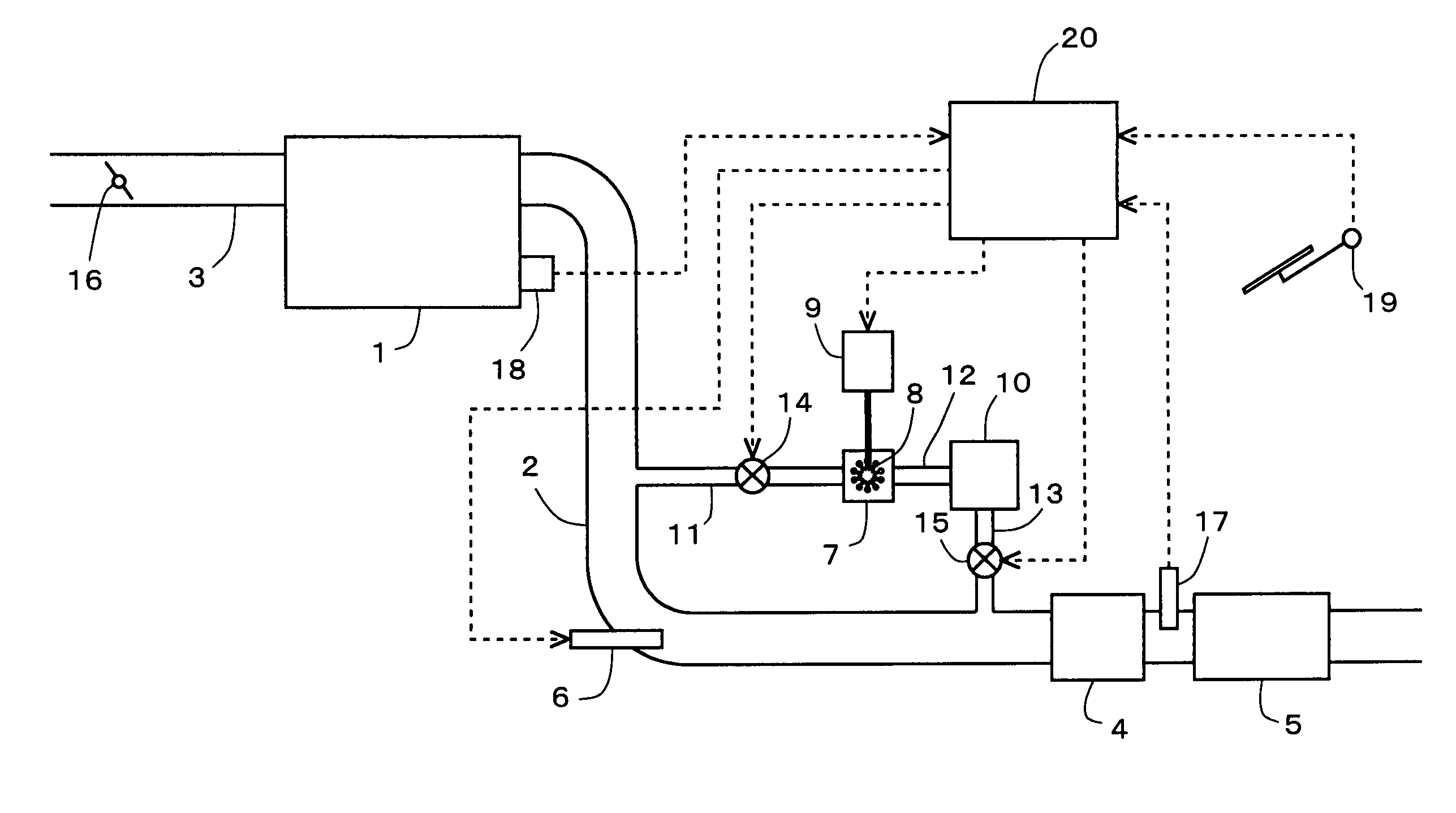
[0033]Here, a description will be made of an exemplary case in which the present invention is applied to a diesel engine for driving a vehicle. FIG. 1 is a diagram showing the general configuration of an air-intake and exhaust system of an internal combustion engine according to this embodiment.

[0034]The internal combustion engine 1 is a diesel engine for driving a vehicle. The internal combustion engine 1 is connected with an intake passage 3 and an exhaust passage 2. A throttle valve 16 is provided in the intake passage 3. An NOx catalyst 4 is provided in the exhaust passage 2. In addition, a filter 5 is provided in the exhaust passage 2 downstream of the NOx catalyst 4.

[0035]A fuel addition valve 6 that adds fuel serving as a reducing agent to the exhaust gas is provided in the exhaust passage 2 upstream of the NOx catalyst 4. A temperature sensor 17 that senses the temperature of the exhaust gas is provided between the NOx catalyst 4 and the filter 5 in the exhaust passage 2.

[00...

embodiment 2

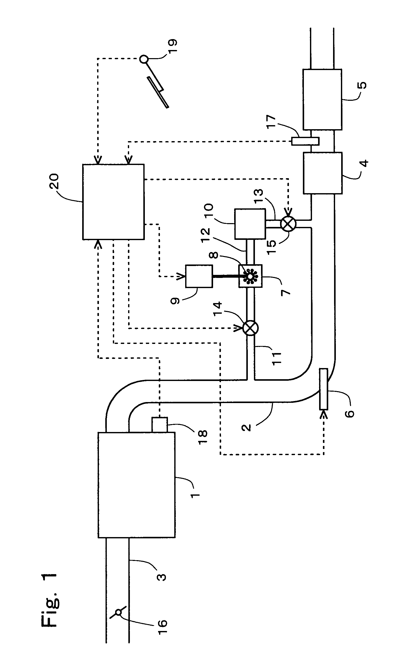
[0062]FIG. 4 is a diagram showing the general configuration of an air-intake and exhaust system of an internal combustion engine according to this embodiment. In this embodiment, the O3 production apparatus 7 is connected with one end of a fourth communication passage 21. The other end of the fourth communication passage 21 is connected to the exhaust passage 2 at a position upstream of the NOx catalyst 4. The fourth communication passage 21 is provided with a third valve 22.

[0063]If the third valve 22 is opened when O3 is being produced by the O3 production apparatus 7, the fourth communication passage 21 is opened, and O3 produced in the O3 production apparatus 7 is supplied to the exhaust gas flowing in the exhaust passage 2. The quantity of O4 supplied to the exhaust gas is controlled by controlling the opening degree of the third valve 22. The third valve 22 is electrically connected to the ECU 20 and controlled by the ECU 20. The configuration other than described above is the...

embodiment 3

[0074]FIG. 6 is a diagram showing the generation configuration of an air-intake and exhaust system of an internal combustion engine according to this embodiment. In this embodiment, the internal combustion engine 1 is mounted on a hybrid vehicle that can selectively use, as the driving power, one or both of the power output of the internal combustion engine 1 and the power output of a motor generator 23. The motor generator 23 is electrically connected with a battery 9. The motor generator 23 can apply voltage to a plasma generation apparatus 8 of an O3 production apparatus 7. The motor generator 23 is electrically connected with an ECU 20 and controlled by the ECU 20. The configuration other than described above is the same as the general configuration of the air-intake and exhaust system of the internal combustion engine according to embodiment 1, therefore like elements will be denoted by like reference numerals, and a description thereof will be omitted.

3 Production Method>

[0075...


PUM

PropertyMeasurementUnit
temperatureaaaaaaaaaa
electrical fieldaaaaaaaaaa
electric poweraaaaaaaaaa

Abstract

An object of the present invention is to produce O3 to be supplied to the exhaust gas of an internal combustion engine while suppressing deterioration of the fuel economy. An O3 production apparatus according to the present invention is an O3 production apparatus that produces O3 to be supplied to the exhaust gas of an internal combustion engine by generating a plasma, when the operation state of the internal combustion engine is a decelerating operation state in which the engine load becomes lower.

Description

[0001]This application is the national phase application under 35 U.S.C. §371 of PCT international application No. PCT / JP2008 / 057559 filed on Apr. 11, 2008, which claims priority to Japanese patent application No. 2007-118566 filed on Apr. 27, 2007, the contents of which are incorporated herein by reference.TECHNICAL FIELD[0002]The present invention relates to an O3 production apparatus that produces O3 to be supplied to the exhaust gas of an internal combustion engine and to an exhaust gas purification system for an internal combustion engine.BACKGROUND ART[0003]An O3 production apparatus that produces O3 to be supplied to the exhaust gas of an internal combustion engine by generating a plasma has been known. Supply of O3 produced by such an O3 production apparatus to the exhaust gas promotes oxidation of NO in the exhaust gas, whereby NO can be changed into NO2. NO2 is stored more easily in an NOx storage reduction catalyst (which will be simply referred to as an “NOx catalyst” he...

Claims


Application Information

Patent Timeline
Patent Type & Authority Patents(United States)
IPC IPC(8): F01N3/00
CPCB01D53/9409B01D53/944B01D53/9495B01D53/96C01B13/10F01N3/0814F01N3/0842B01D2251/104B01D2255/91B01D2258/012F01N3/023F01N2240/28F01N2240/38F01N2250/02F01N2610/03
Inventor TSUJIMOTO, KENICHIHIROTA, SHINYA
Owner TOYOTA JIDOSHA KK
Why Eureka
Try Eureka