
Power plant start-up method and method of venting the power plant

a power plant and start-up method technology, applied in the direction of engine starters, turbine/propulsion engine ignition, machines/engines, etc., can solve the problem of large excess oxygen in the exhaust stream

Active Publication Date: 2012-09-18
GE INFRASTRUCTURE TECH INT LLC
View PDF87 Cites 79 Cited by
  • Summary
  • Abstract
  • Description
  • Claims
  • Application Information

AI Technical Summary

Problems solved by technology

This often results in an exhaust stream with large amounts of excess oxygen.

Method used


Image

  • Power plant start-up method and method of venting the power plant
  • Power plant start-up method and method of venting the power plant
  • Power plant start-up method and method of venting the power plant

Examples


Embodiment Construction

[0009]In the following description, numerous specific details are given to provide a thorough understanding of embodiments. The embodiments can be practiced without one or more of the specific details, or with other methods, components, materials, etc. In other instances, well-known structures, materials, or operations are not shown or described in detail to avoid obscuring aspects of the embodiments.

[0010]Reference throughout this specification to “one embodiment,”“an embodiment,” or “embodiments” means that a particular feature, structure, or characteristic described in connection with the embodiment is included in at least one embodiment. Thus, the appearances of the phrases “in one embodiment” or “in an embodiment” in various places throughout this specification are not necessarily all referring to the same embodiment. Furthermore, the particular features, structures, or characteristics may be combined in any suitable manner in one or more embodiments.

[0011]Recent requirements i...


PUM


Abstract

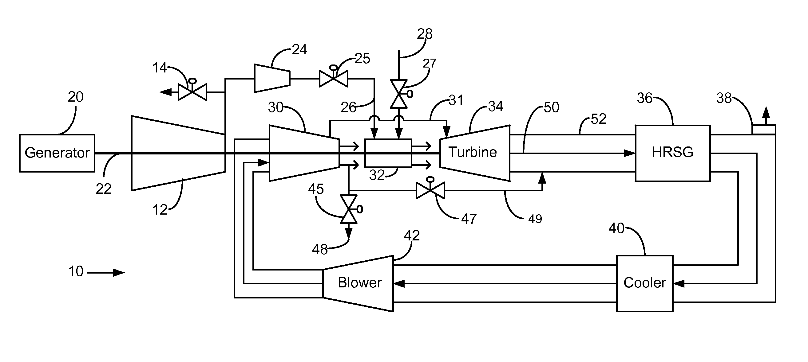
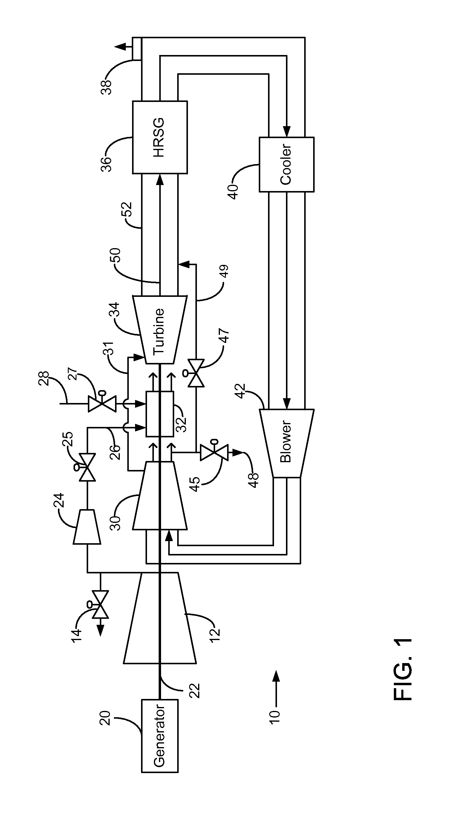
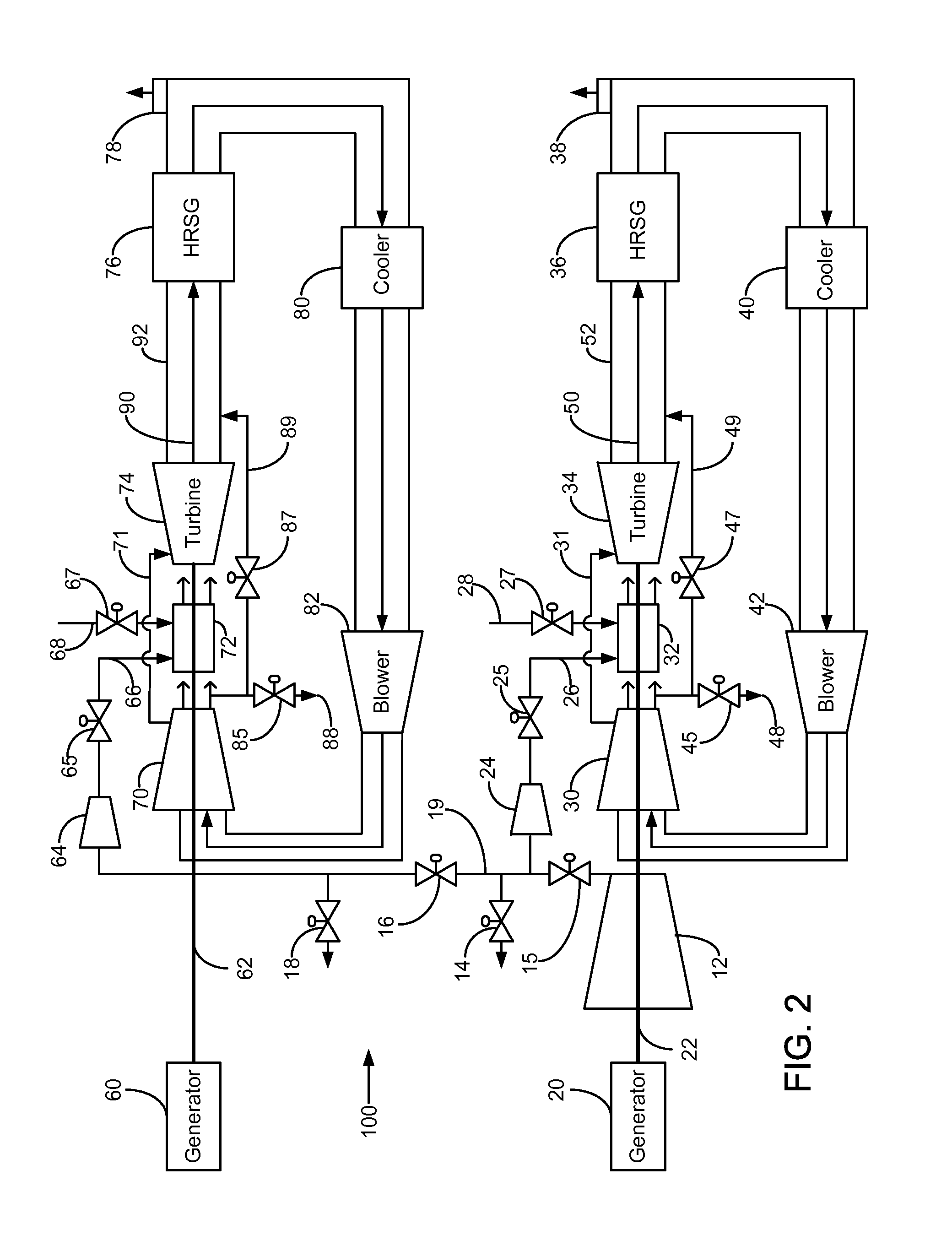
Ambient air is compressed into a compressed ambient gas flow and delivered to a turbine combustor. At least one of an exhaust port, a bypass conduit, or an extraction conduit is opened to vent the power plant. A turbine shaft is rotated at an ignition speed and a fuel stream is delivered to the turbine combustor for mixing with the compressed ambient gas flow to form a combustible mixture. The combustible mixture is burned and forms a recirculated gas flow that drives the turbine. The recirculated gas flow is recirculated using the recirculation loop. The turbine is operated at a target operating speed and then reaches substantially stoichiometric combustion. At least a portion of the recirculated gas flow is extracted using an extraction conduit that is fluidly connected to the turbine compressor.

Description

BACKGROUND OF THE INVENTION[0001]The subject matter of the present disclosure relates generally to the field of electric power plants, and more particularly to methods of starting-up stoichiometric exhaust gas recirculation turbine systems. Various types of gas turbine systems are known and in use for electricity generation in power plants. Typically, the gas turbine systems include a turbine compressor for compressing an air flow and a turbine combustor that combines the compressed air with a fuel and ignites the mixture to generate an exhaust gas. The exhaust gas may then be expanded through a turbine, thereby causing the turbine to rotate, which in turn may be connected to a turbine generator via a turbine shaft, for power generation. Gas turbines have traditionally used excess air within the combustion process to control turbine temperatures and manage undesirable emissions. This often results in an exhaust stream with large amounts of excess oxygen.[0002]Accordingly, there exis...

Claims


Application Information

Patent Timeline
Patent Type & Authority Patents(United States)
IPC IPC(8): F02C7/08F02G3/00F02C6/00F02C6/04F02G1/00
CPCF02C7/277F01D13/02F01D15/10F01D19/00F02C6/06F02C7/18F02C9/52F02C3/36F05D2260/85F05D2270/061F05D2220/76F05D2270/082Y02T50/60
Inventor DION OUELLET, NOEMIESNOOK, DANIEL DAVIDWICHMANN, LISA ANNEDRAPER, SAMUEL DAVIDRITTENHOUSE, SCOTT ALLEN
Owner GE INFRASTRUCTURE TECH INT LLC
Learn More