
Method, system and base station using frame configuration which supports relay for wireless transmission

a wireless transmission and frame configuration technology, applied in the field of wireless communication, can solve the problems of sharing wireless access services, sharp reduction of coverage area, and reducing service quality, so as to increase resource utilization ratio and reduce delay

Active Publication Date: 2012-09-11
DATANG MOBILE COMM EQUIP CO LTD
View PDF17 Cites 11 Cited by
  • Summary
  • Abstract
  • Description
  • Claims
  • Application Information

AI Technical Summary

Benefits of technology

This approach effectively decreases delay, enhances resource utilization, and supports seamless coverage and multi-hop relays, ensuring compatibility with TD-SCDMA systems while minimizing resource wastage and improving system flexibility.

Problems solved by technology

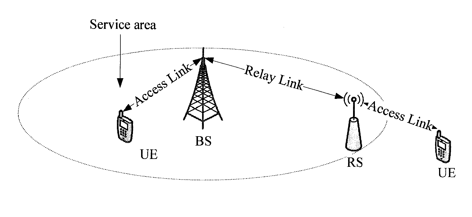
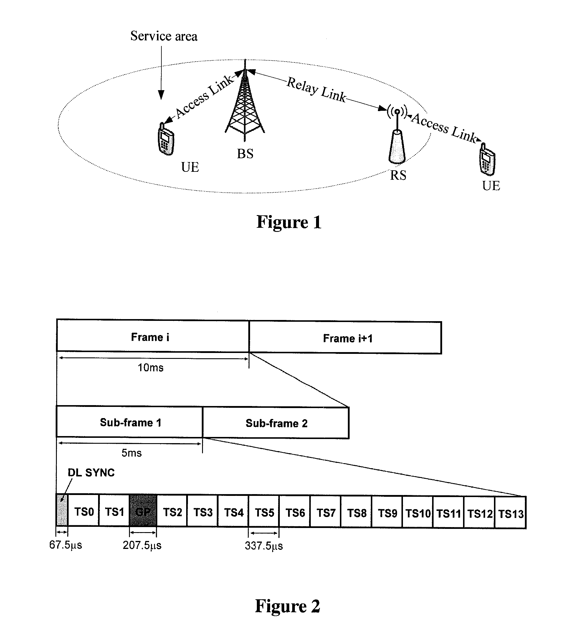
However, a mobile station may quite possibly locate outside the service area and can not therefore share the wireless access service due to its mobility.
Even if the UE locates in the service area, the signal transmission may be possibly obstructed by obstacles on transmission paths, which reduces the Quality of Service.
These two factors may cause a sharp reduction of the coverage area, and the number of base stations / access points may influence construction and operating cost of the network to a large extent.
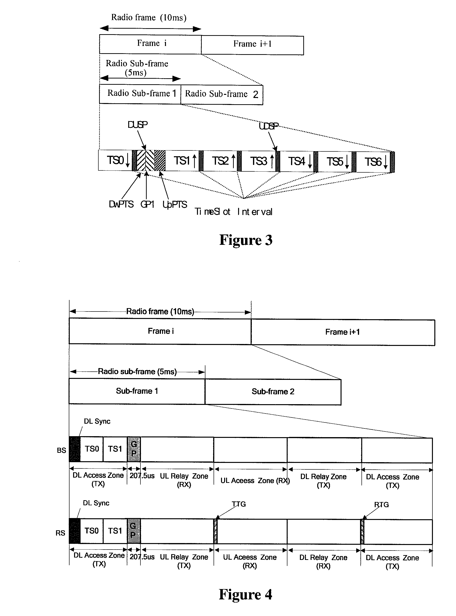
(1) Increasing the delay. Taking a BS transmitting downlink traffic as an example: when the downlink traffic arrives at the BS, the BS may transmit the downlink traffic at the beginning time of a downlink subframe in the original system frame structure. However, the BS may transmit the downlink traffic only in the DownLink (DL) Access Zone of the B3G frame structure supporting Relay, which increases the delay virtually and makes it difficult to meet the rigorous requirements for delay in B3G, as particularly illustrated in FIG. 5.
(2) Wasting resource. In the case that traffic is little and little bandwidth is required in a relay link, bandwidth in the whole Relay zone shall be allocated to the relay link if the original frame structure supporting Relay is utilized for data transmission, which may cause a severe resource wasting, as particularly illustrated in FIG. 6.

Method used


Image

  • Method, system and base station using frame configuration which supports relay for wireless transmission
  • Method, system and base station using frame configuration which supports relay for wireless transmission
  • Method, system and base station using frame configuration which supports relay for wireless transmission

Examples


Embodiment Construction

[0037]The basic idea of an embodiment of the present invention lies in that a manner combining time division multiplex and frequency division multiplex in a broadband TDD system, which can implement feasible granularity and flexibility and effectiveness of resource scheduling.

[0038]In order to make those skilled in the art better understand the technical solution according to embodiments of the present invention, the present invention is described in detail hereinafter with reference to the attached drawings and the embodiments. As illustrated in FIG. 7, a method according to an embodiment of the present invention includes:

[0039]Step 701: Setting at least one time slot in a subframe as a hybrid zone; and

[0040]Step 702: Performing data transmission in a frequency division multiplex manner in the hybrid zone.

[0041]In particular, in the B3G frame structure according to the conventional art, each frame, 10 ms, is divided into two 5 ms subframes, and each subframe includes one DownLink S...


PUM


Abstract

A method using a frame structure which supports relay for wireless transmission, which divides the time slots of a sub-frame into some zones, in which the data is transmitted using the manner of TDD, wherein further including that at least one time slot in a sub-frame is set as a hybrid zone; the transmission of the data is realized through frequency division multiplexing the access link and relay link in the hybrid zone of the sub-frame; and also the multi-hop relay is supported under the two work manners of relay in sub-frame and relay in frame.

Description

CROSS-REFERENCE TO RELATED APPLICATIONS[0001]This application is the National Stage of International Application No. PCT / CN2008 / 071578, filed on Jul. 8, 2008, which claims the priority to Chinese Patent Application No. 200710118573.4, filed with the Chinese Patent Office on Jul. 9, 2007 and entitled “METHOD FOR WIRELESS TRANSMISSION BY USING FRAME STRUCTURE SUPPORTING RELAY AND SYSTEM THEREOF”, which is hereby incorporated by reference in its entirety.FIELD OF THE INVENTION[0002]The present invention relates to the technical field of wireless communication and particularly to a method for wireless transmission by using a frame structure supporting relay, a system and a base station thereof.BACKGROUND OF THE INVENTION[0003]In the 3rd Generation (3G) and the Beyond 3rd Generation (B3G) communication systems, the coverage area is an important aspect for a wireless access system, and the wireless access system performs coverage of its service area generally through base stations or acce...

Claims


Application Information

Patent Timeline
Patent Type & Authority Patents(United States)
IPC IPC(8): H04J3/00
CPCH04B7/2606H04B7/2656H04L5/0005H04L5/143H04B7/155
Inventor ZHANG, GUANGHUIXIE, YONGBINWANG, YINGMINSUN, SHAOHUIYU, YANG
Owner DATANG MOBILE COMM EQUIP CO LTD
Learn More