
Image forming apparatus performing function related to external apparatus

a technology of external apparatus and forming apparatus, which is applied in the direction of digital output to print units, digitally marking record carriers, instruments, etc., can solve the problems of user conducting a predetermined operation, complicated operations, and complicated operations, and achieve the effect of not complicated operations

Active Publication Date: 2012-09-11
KONICA MINOLTA BUSINESS TECH INC
View PDF19 Cites 0 Cited by
  • Summary
  • Abstract
  • Description
  • Claims
  • Application Information

AI Technical Summary

Benefits of technology

"The present invention aims to provide an image forming apparatus that can easily perform functions related to external devices without complicated operations. To achieve this, the image forming apparatus includes a connection unit for inserting and removing an external memory that stores function information and parameters for processing documents related to the external device. The read unit reads the function information from the external memory, and the execution unit executes the process for the document using the function information. This allows the image forming apparatus to perform the function without needing complicated settings or accessing confidential information, improving operability and security."

Problems solved by technology

Consequently, there arises a problem of complicated operations.
Consequently, there arises a problem of more complicated operations.
Even in the case of using the technique disclosed in Reference 1, however, there arises a problem that the user must conduct a predetermined operation in order to set the parameters.
Even in the case of using the technique disclosed in Reference 1, further, there arises a problem that the user must conduct the operation required for exertion of the function after the setting of the parameters.

Method used


Image

  • Image forming apparatus performing function related to external apparatus
  • Image forming apparatus performing function related to external apparatus
  • Image forming apparatus performing function related to external apparatus

Examples


first embodiment

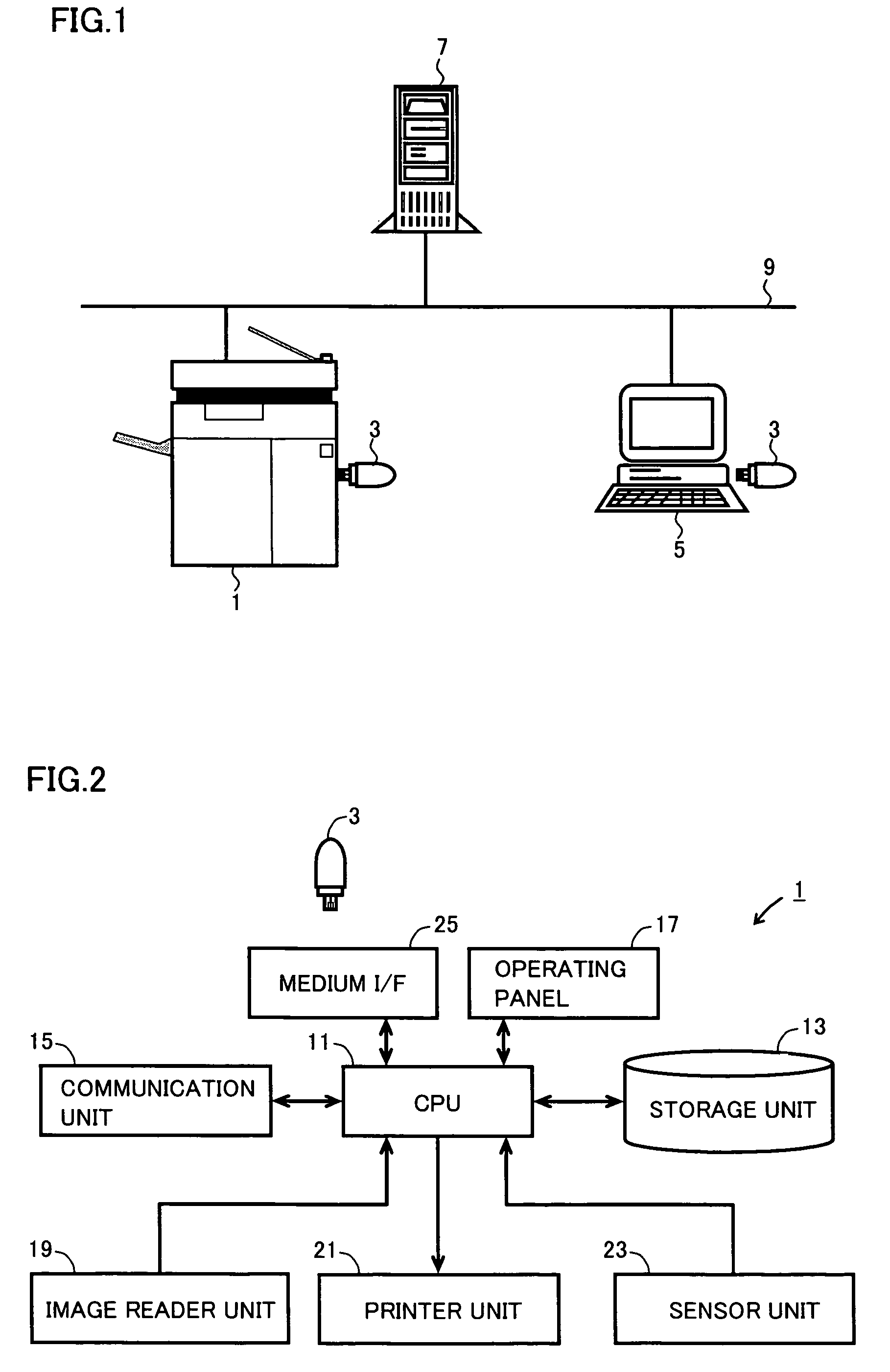
[0024]With reference to FIG. 1, an image forming system according to one embodiment of the present invention has a configuration that an MFP (Multi Function Peripheral) 1 serving as an image forming apparatus, a PC (Personal Computer) 5 serving as another apparatus and a server 7 serving as an external apparatus are connected to one another through a network 9. A USB (Universal Serial Bus) memory 3 serving as an external memory can be inserted into / removed from each of MFP 1 and PC 5. Each of MFP 1 and PC 5 can read / write information from / to USB memory 3. Herein, the image forming apparatus is not limited to an MFP as long as it has a function of accessing the external apparatus and a function related to the external apparatus. Examples of the image forming apparatus may include a copying machine, an image data transmitting apparatus and the like. Moreover, the external memory is not limited to a USB memory, and examples thereof may include an IC card, a portable telephone having a ...

second embodiment

[0049]As a second embodiment of the present invention, next, description will be given of a case where USB memory 3 stores plural pieces of function information in addition to the PullPrint function.

[0050]FIG. 6 is a flowchart showing a specific example of a flow of processes executed in MFP 1 in accordance with the second embodiment of the present invention. The processes shown in the flowchart of FIG. 6 are also realized in such a manner that CPU 11 of MFP 1 reads and executes the programs stored in storage unit 13 so as to control the respective units shown in FIG. 4.

[0051]With reference to FIG. 6, the processes executed in steps S101 to S105 are similar to those described in the first embodiment. In the second embodiment, USB memory 3 stores the plural pieces of function information including the PullPrint function. In this case (YES in step S301), UI display unit 40 executes a process for displaying on operating panel 17 a select menu for selecting target function information t...

third embodiment

[0061]As a third embodiment of the present invention, next, description will be given of a case where MFP 1 uses the history information stored in USB memory 3.

[0062]FIG. 8 is a flowchart showing a specific example of a flow of processes executed in MFP 1 in accordance with the third embodiment of the present invention and showing details of the process for performing the PullPrint function in step S111.

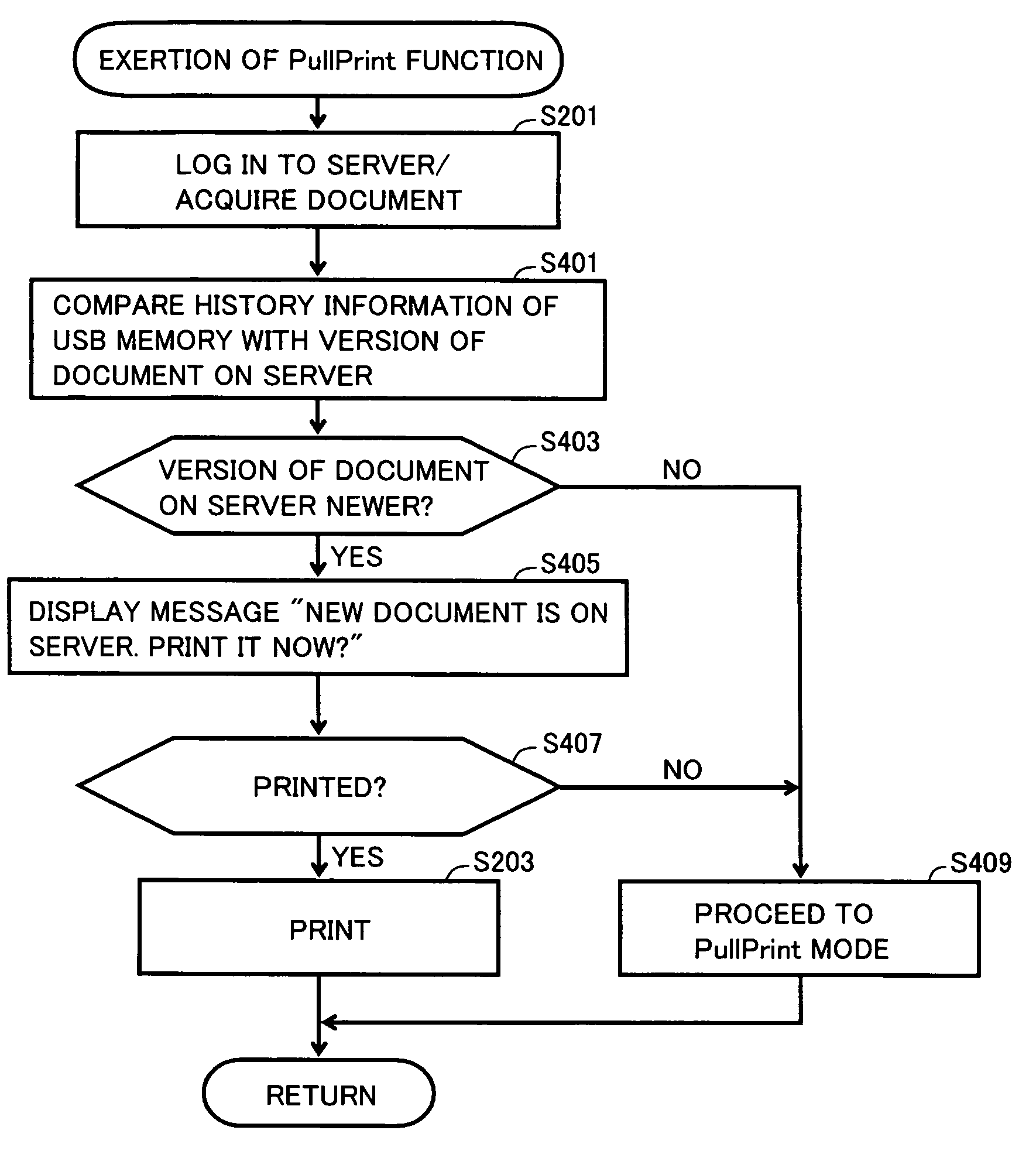
[0063]With reference to FIG. 8, in the third embodiment, the process in step S201 is executed as described above, so that acquisition unit 301 of network unit 30 acquires a document from specified server 7. Comparison unit 303 of acquisition unit 301 compares a version of the document contained in the history information with a version of the document registered in server 7 (step S401). Preferably, the version of the document contained in the history information, which is subjected to the comparison herein, is a version of a document in the previous process.

[0064]It is assumed that t...


PUM


Abstract

A USB memory stores, as function information, a function of processing a document and a place where the document is registered. An MFP includes a read unit for reading function information from the USB memory inserted into the MFP, a specifying unit for specifying required information from among the function information, an acquisition unit for accessing a server with the use of the specified information to acquire a target document to be processed, a setting unit for making a setting for performing a PullPrint function, which corresponds to the aforementioned function, with the use of the information, and a print control unit for executing a process for printing the acquired document on the basis of the setting made by the setting unit.

Description

[0001]This application is based on Japanese Patent Application No. 2007-188406 filed with the Japan Patent Office on Jul. 19, 2007, the entire content of which is hereby incorporated by reference.BACKGROUND OF THE INVENTION[0002]1. Field of the Invention[0003]The present invention relates to an image forming apparatus, and a method for controlling the image forming apparatus. In particular, the present invention relates to an image forming apparatus performing a function related to an external apparatus with the use of information stored in an external memory, and a method for controlling the image forming apparatus.[0004]2. Description of the Related Art[0005]Occasionally, a function of an image forming apparatus such as an MFP (Multi Function Peripheral) has been exerted by a method unique to a user. In such a case, first, parameters required for the exertion of the function by the method are set for the image forming apparatus; thus, the image forming apparatus performs the funct...

Claims


Application Information

Patent Timeline
Patent Type & Authority Patents(United States)
IPC IPC(8): G06K15/00
CPCH04N1/00204H04N1/00244H04N1/00278H04N1/00347H04N1/00973H04N1/32122G06F3/1222G06F3/1238G06F3/1267G06F3/128H04N2201/0039H04N2201/0094H04N2201/3202G06F3/1273G06F3/1288
Inventor SUGIMOTO, TETSUYA
Owner KONICA MINOLTA BUSINESS TECH INC
Learn More