Support for the holding and positioning of a utility load in space

a technology for space and utility loads, applied in lighting and heating apparatus, curtain suspension devices, lighting support devices, etc., can solve the problems of limited space for many applications, and the utility load cannot be positioned on a spherical surface, and achieve the effect of wide adjustment rang

Inactive Publication Date: 2012-09-04
MAQUET GMBH
View PDF19 Cites 10 Cited by
  • Summary
  • Abstract
  • Description
  • Claims
  • Application Information

AI Technical Summary

Benefits of technology

[0005]The invention has as its object the provision of a support of the previously mentioned kind which on one hand permits an at least nearly force free adjustment of the utility load without the introduction of moments to the base, and which on the other hand offers a wide adjustment range for a free positioning of the utility load in space.

Problems solved by technology

A disadvantage, however, is that with this system the utility load can only be positioned on a spherical surface.
This for many applications is a relatively strong spatial limitation.

Method used


Image

  • Support for the holding and positioning of a utility load in space
  • Support for the holding and positioning of a utility load in space
  • Support for the holding and positioning of a utility load in space

Examples


Embodiment Construction

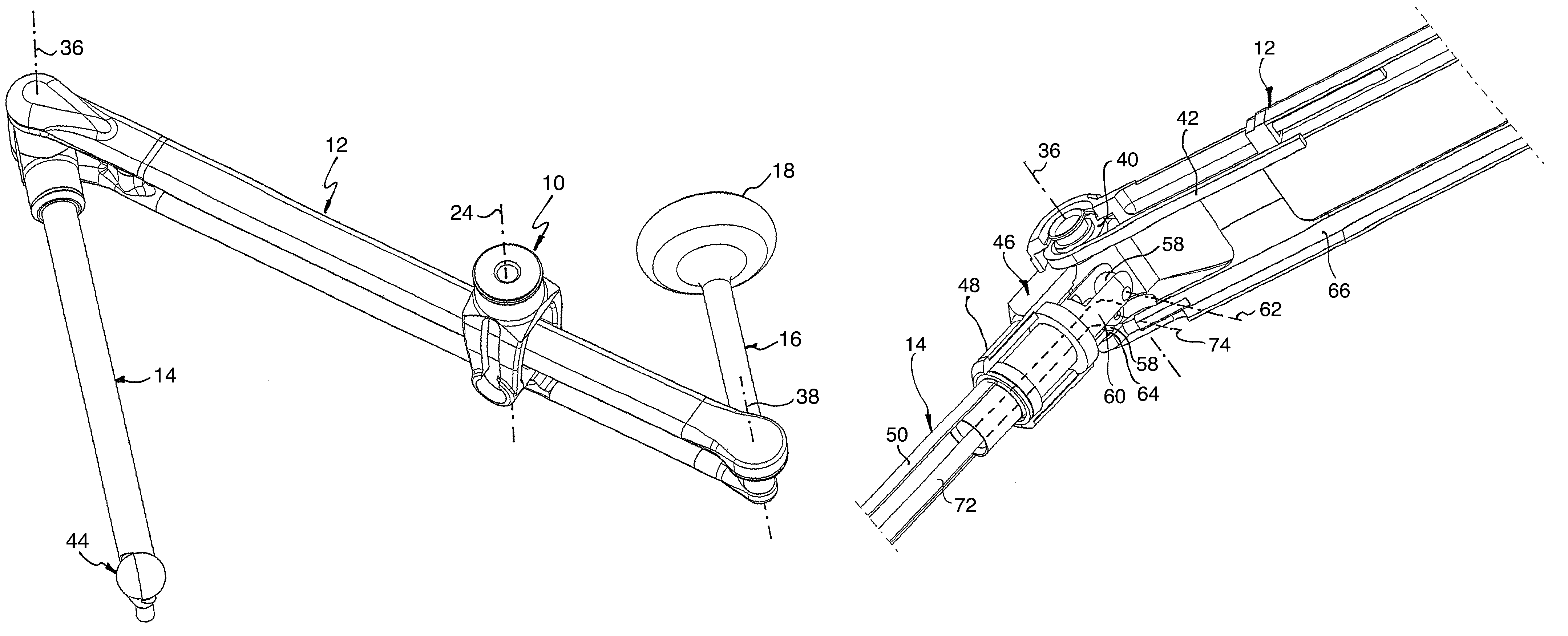
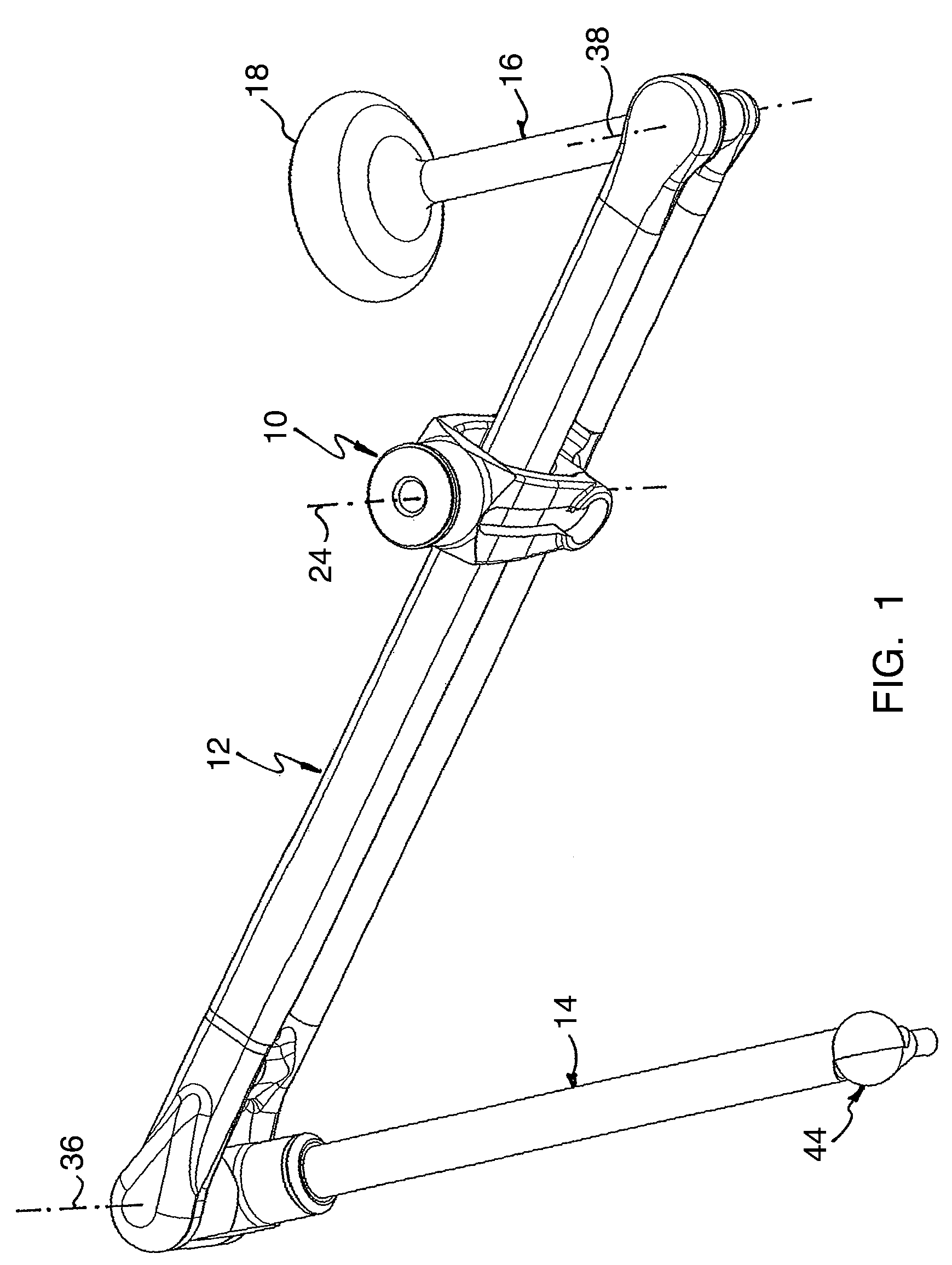
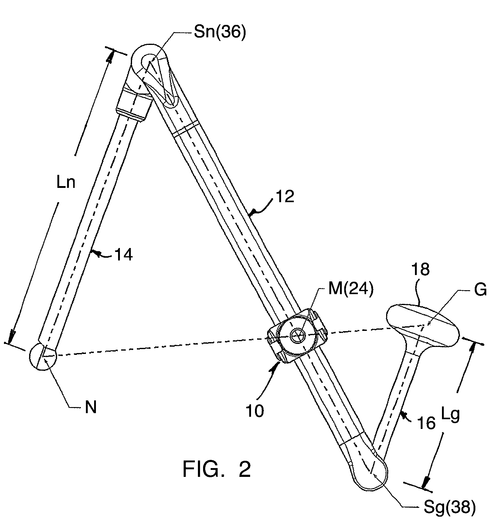
[0020]The ceiling mounted support partially schematically illustrated in FIG. 1 includes a base 10 and an elongated supporting arm 12, to the two ends of which supporting arm are hingedly connected a first connector arm 14 for holding a non-illustrated utility load and a second connector arm 16 which carries a counterweight 18. The counterweight can in a non-illustrated way be adjustable in the longitudinal direction of the second connector arm 16.

[0021]The base includes a pedestal part 20 (FIG. 5) fixable to a space ceiling, on which pedestal part a fork-shaped bearing part 22 is rotatably supported for movement about a first vertical axis 24. Between the fork legs 26 of the bearing part 24 the supporting arm 12 is swingably supported (FIG. 5) on a shaft journal 28 for swinging movement about a horizontal axis 30.

[0022]The supporting arm 12 comprises an upper strut 32 and a lower strut 34 between which the first connector arm 14 is swingable about a third axis 36 and the second con...


PUM


Abstract

In a support for holding and positioning a utility load in space having a base (10) and an elongated supporting arm (12) which between its longitudinal ends is swingably supported on the base (10) for swinging moment about a vertical first axis (24) and about a horizontal second axis (30) which intersects the vertical first axis (24), the supporting arm (12) carrying on one side of the second axis the utility load and on the other side of the second axis carrying a counterweight compensating for the utility load, the utility load being arranged on a first connector arm (14) which is pivotally supported at one end of the supporting arm (12) for moment about a third axis (36), the counterweight (18) being arranged on a second connector arm which is swingably supported on the other end of the supporting arm (12) for movement about a fourth axis (38), the third and fourth axis being parallel to one another, the spacing (Ln) between the engagement point (N) of the utility load and the first connector arm (14) and the third axis (38) being equal to the spacing between the third axis (38) and the vertical axis (24), the spacing (Lg) measured in the longitudinal direction of the second connector arm (16) between the center of gravity (G) of the counterweight (18) and the fourth axis (38) being equal to the spacing between a fourth axis (38) and the vertical first axis (24), and the two connector arms (14, 16) being so coupled with one another by a coupling means that in any pivoted position they are directed antiparallel to one another.

Description

CROSS REFERENCE TO RELATED APPLICATION[0001]Applicant hereby claims foreign priority benefits under U.S.C. §119 from German Patent Application No. 10 2008 015 210.2 filed on Mar. 20, 2008, the contents of which are incorporated by reference herein.TECHNICAL FIELD[0002]The invention concerns a support for the holding and positioning of a utility load in space with a base and an elongated supporting arm, which supporting arm is supported between its longitudinal ends on the base for rotational movement about a vertical first axis and for a swinging movement about a horizontal second axis, which horizontal second axis intersects the vertical first axis, with the supporting arm on one side of the second axis carrying the utility load and on the other side of the second axis carrying a counterweight compensating for the utility load.BACKGROUND OF THE INVENTION[0003]A support of the previously mentioned kind, which is known from the state of the art, has the advantage by way of the counte...

Claims


Application Information

Patent Timeline
Patent Type & Authority Patents(United States)
IPC IPC(8): E04G3/00
CPCF16M11/04F16M11/16F16M11/2092A61G13/00F16M2200/04F16M2200/068F21V27/00F21W2131/205F21V17/10F21V21/14
Inventor KOCH, GUIDOPFEUFFER, REINHARD
Owner MAQUET GMBH
Why Eureka
Try Eureka