Smoke sensor of the sound wave type including a smoke density estimation unit
a technology of smoke density and sound wave, applied in the field of smoke sensors, can solve the problems of high attenuation amount of ultrasound waves passing through the monitoring space caused by increased smoke density therein, and achieve the effects of increasing sensitivity, increasing the frequency of dilatational waves, and increasing the sn ratio
- Summary
- Abstract
- Description
- Claims
- Application Information
AI Technical Summary
Benefits of technology
Problems solved by technology
Method used
Image
Examples
first embodiment
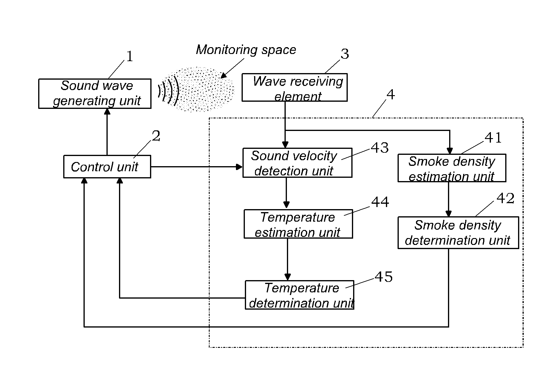
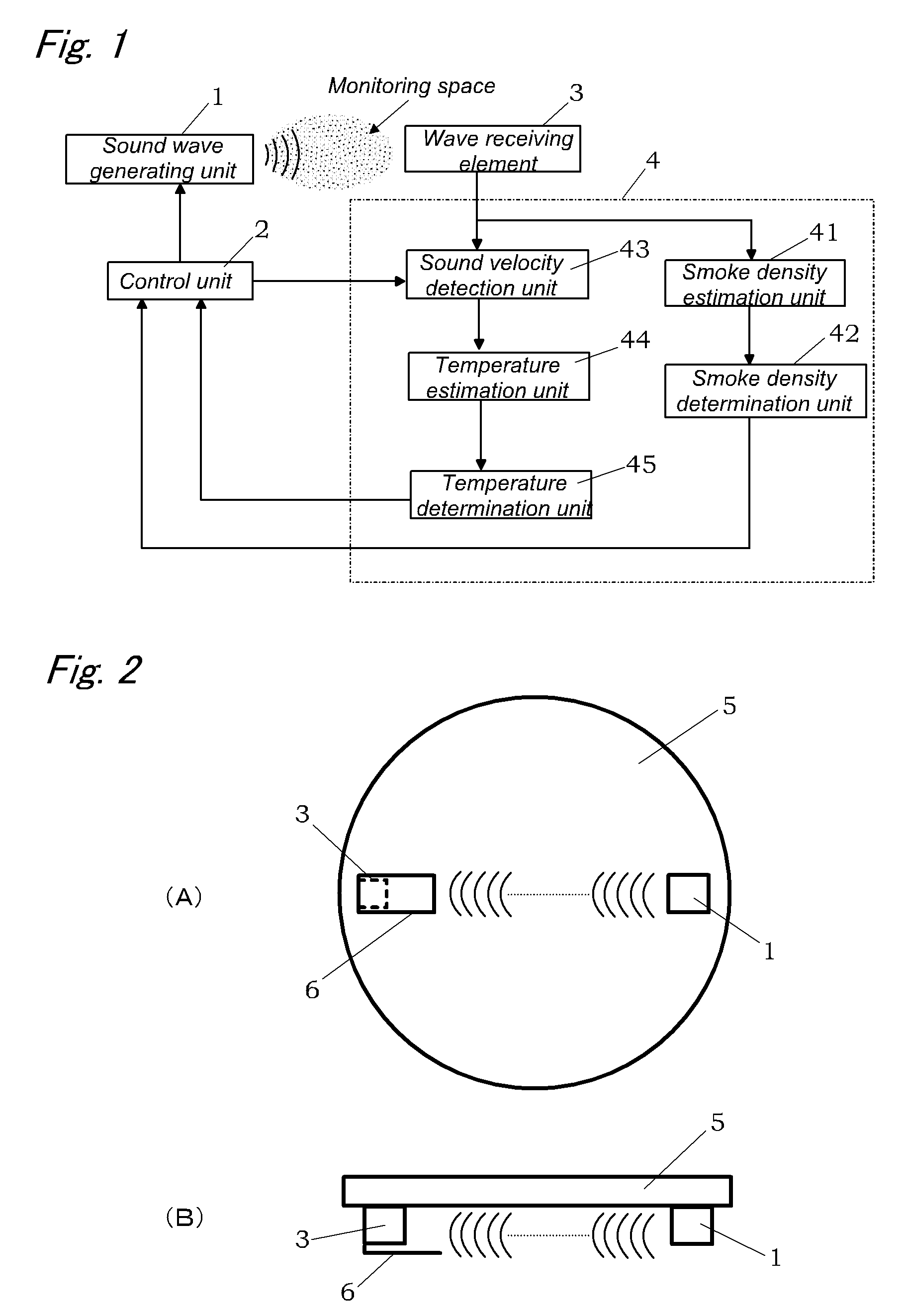
[0094]As shown in FIG. 1, the fire sensor of the present embodiment is mainly configured by a sound wave generating unit 1 that provides an ultrasound wave into a monitoring space, a control unit 2 that controls the sound wave generating unit 1, a wave receiving element 3 serving as an ultrasound wave receiving unit that detects a sound pressure of the ultrasound wave from the sound wave generating unit 1 via the monitoring space, and a signal processing unit 4 that determines whether fire is present based on the output of the wave receiving element 3.
[0095]As shown in FIGS. 2A and 2B, the sound wave generating unit 1 and wave receiving element 3 are disposed opposite each other with a certain spacing therebetween on a circuit substrate 5 composed of a disk-shaped printed circuit board. The control unit 2 and signal processing unit 4 are provided on the circuit substrate 5. In FIG. 2A, a reference numeral 6 stands for a sound shielding wall provided around the wave receiving element...
second embodiment
[0111]The fire sensor of the present embodiment is substantially identical to that of the first embodiment, except that the configurations of the control unit 2 and signal processing unit 4 are different, as shown in FIG. 5. Therefore, structural elements identical to those of the first embodiment are assigned with identical reference numerals and redundant explanation thereof is omitted.
[0112]As shown in FIG. 6, preliminary experiments have confirmed that the relationship between the output frequency of the sound wave generating unit 1 and the unit attenuation ratio of sound pressure differs depending on the type of smoke particles present (floating) in the monitoring space. Here, the attenuation ratio of sound pressure will be defined as (I0−Ix) / I0, where I0 stands for a sound pressure (referred to hereinbelow as “standard sound pressure”) received by the wave receiving element 3 in a state in which smoke particles are not present in the monitoring space and Ix is a sound pressure...
third embodiment
[0128]The fire sensor of the present embodiment is substantially identical to that of the first embodiment, except that a tubular body 50 that narrows the diffusion range of ultrasound waves and has the inner space thereof used as a propagation path for ultrasound waves is disposed between the sound wave generating unit 1 and wave receiving element 3, as shown in FIG. 14A and FIG. 14B. Therefore, structural elements identical to those of the first embodiment are assigned with identical reference numerals and redundant explanation thereof is omitted.
[0129]The tubular body 50 is disposed in at least part of the propagation path of ultrasound waves in the monitoring space. More specifically the tubular body 50 of the present embodiment has an angular tubular structure of an almost rectangular parallelepiped in which two end surface in the longitudinal direction are open, and one end surface in the longitudinal direction (right end surface in FIG. 14A) is disposed close to the sound wav...
PUM
 Abstract
Description
Claims
Application Information
 - R&D
- Intellectual Property
- Life Sciences
- Materials
- Tech Scout
- Unparalleled Data Quality
- Higher Quality Content
- 60% Fewer Hallucinations
Browse by: Latest US Patents, China's latest patents, Technical Efficacy Thesaurus, Application Domain, Technology Topic, Popular Technical Reports.
© 2025 PatSnap. All rights reserved.Legal|Privacy policy|Modern Slavery Act Transparency Statement|Sitemap|About US| Contact US: help@patsnap.com


