Circuit arrangement for producing short electrical pulses

a circuit arrangement and short circuit technology, applied in the direction of pulse generators, electrical apparatus, electronic switching, etc., can solve the problems of very low power consumption and low complexity of circuit arrangements, and achieve the effect of low power consumption and low complexity

Active Publication Date: 2012-08-28
KROHNE MESSTECHNICK GMBH & CO KG
View PDF11 Cites 1 Cited by
  • Summary
  • Abstract
  • Description
  • Claims
  • Application Information

AI Technical Summary

Benefits of technology

[0008]A circuit arrangement in accordance with the present invention for producing short electrical pulses, as described herein, can include a logic gate with a very short gate transit time having a clock signal being supplied to a trigger input thereof as a trigger signal, and with an output signal, based on the trigger signal, being generated at an output of the logic gate as a short electrical pulse. Such circuit arrangement has major advantages over known circuit arrangements.
[0009]For example, such circuit arrangement is of very low complexity, and of very low power consumption.
[0013]As noted above, the circuit arrangement can be of low circuit complexity. This is not contradicted, when according to another embodiment, a pulse shaper network, used to shorten the duration of the generated short electrical pulses, is connected downstream of the output of the logic gate that generates the output signal. A fundamental advantage is based on the use of very short logic gate transit times. However, if short electrical pulses need be employed and which cannot be generated by using such short logic gate transit times, the above described downstream connection of a corresponding pulse shaper network advantageously provides such a feature.

Problems solved by technology

For example, such circuit arrangement is of very low complexity, and of very low power consumption.

Method used


Image

  • Circuit arrangement for producing short electrical pulses
  • Circuit arrangement for producing short electrical pulses
  • Circuit arrangement for producing short electrical pulses

Examples


Embodiment Construction

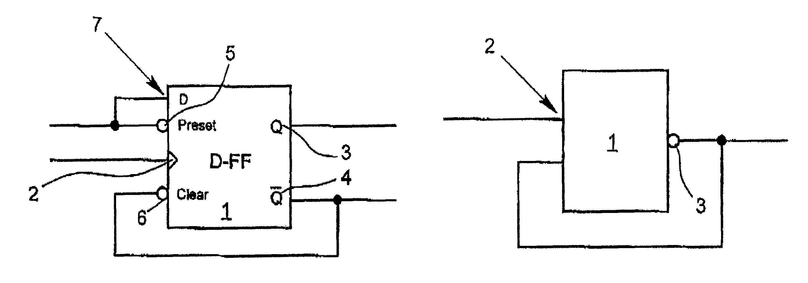
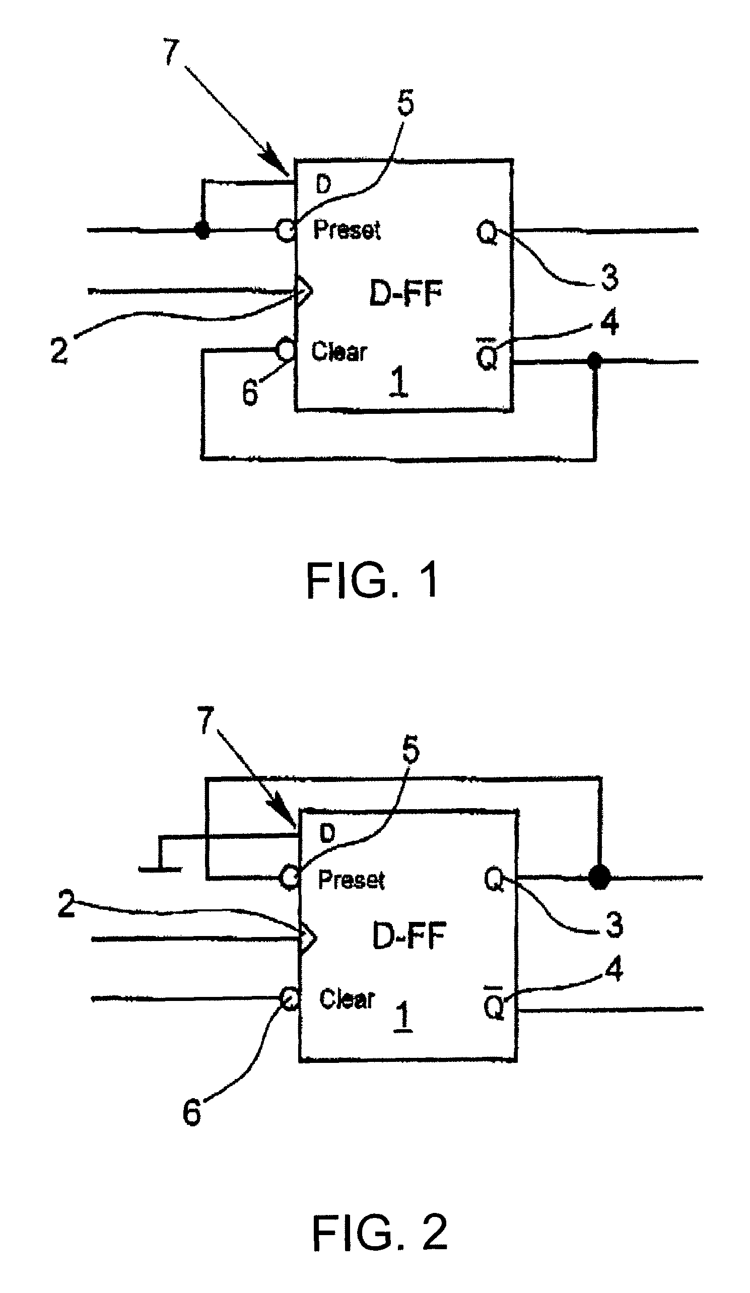
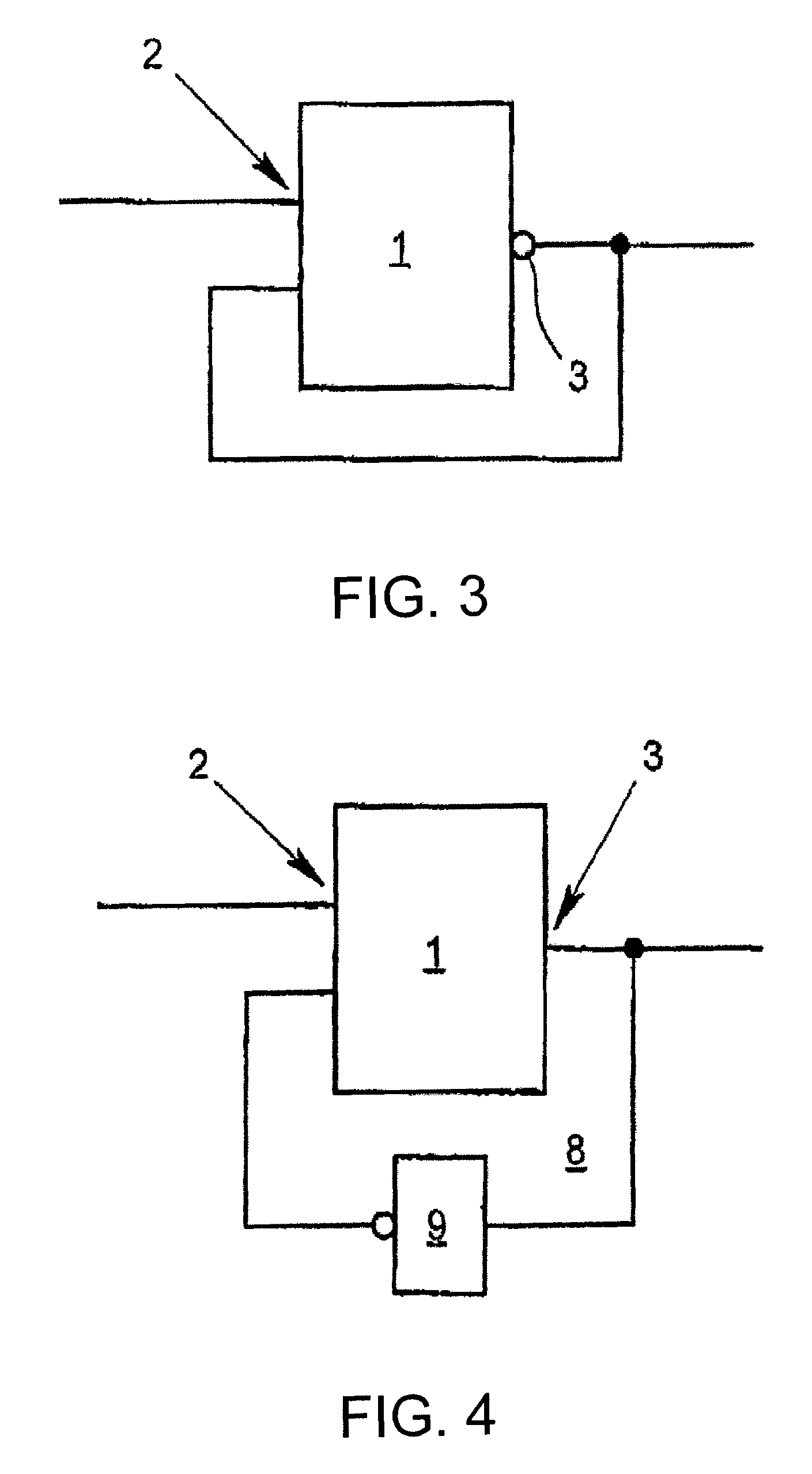
[0021]The accompanying figures show various exemplary embodiments for circuit arrangements for producing short electrical pulses, according to the present invention. A logic gate 1 with a very short gate transit time is common to all of the illustrated embodiments. In all embodiments, a clock signal CLK, is supplied to a trigger input 2 of the logic gate 1, as a trigger signal, wherein an output signal generated by the trigger signal is provided at an output 3 of the logic gate 1 or at outputs 3 or 4 of the logic gate 1 and is provided as a short electrical pulse. The generated short electrical pulses can be referred to as baseband pulses.

[0022]Preferably, but not necessarily, the logic gate 1 is an ESD-protected logic gate. Advantageously, such configuration provides an inherent ESD resistance for the circuit arrangement.

[0023]In the embodiments shown in FIGS. 1 and 2, the logic gate 1 is a high-speed D-flip-flop D-FF having a clear input 5 and a preset input 6.

[0024]FIG. 1 shows t...


PUM


Abstract

A circuit arrangement for producing short electrical pulses, including a logic gate (1) with a very short gate transit time and having a clock signal being supplied to a trigger input (2) of the logic gate (1) as a trigger signal. An output signal based on the trigger signal is generated as a short electrical pulse at an output (3) or at one output (3 or 4) or at both outputs (3 and 4) of the logic gate (1).

Description

BACKGROUND OF THE INVENTION[0001]1. Field of Invention[0002]The invention relates to a circuit arrangement for producing short electrical pulses.[0003]2. Description of Related Art[0004]Short electrical pulses are employed in many areas of communications engineering and measurement engineering, and for example also in liquid level measurement engineering.[0005]A plurality of circuit arrangements are known for producing short electrical pulses, for example, as described in German Patent Application 103 59 441, PCT Patent Application WO 2007 / 008,454, and U.S. Pat. Nos. 4,442,362 and 6,087,871.[0006]Accordingly, although there may exist a plurality of circuit arrangements for producing short electrical pulses, there is still a need for improved circuit arrangements of this type.SUMMARY OF THE INVENTION[0007]In view of the foregoing, a primary object of the present invention is to provide a novel circuit arrangement for producing short electrical pulses.[0008]A circuit arrangement in ac...

Claims


Application Information

Patent Timeline
Patent Type & Authority Patents(United States)
IPC IPC(8): H03K17/16H03K19/003
CPCH03K3/0315H03K2005/00293
Inventor GERDING, MICHAEL
Owner KROHNE MESSTECHNICK GMBH & CO KG
Why Eureka
Try Eureka