
Method and device for the spatially resolved detection and reconstruction of objects by means of microwaves

a technology of spatial resolution and detection and reconstruction, applied in the direction of measurement devices, radio wave reradiation/reflection, using reradiation, etc., can solve the problems of limited resolution capability of conventional microwave methods, object motion must be preserved, and apparatuses of this kind are extremely complex in mechanical terms, so as to achieve the effect of improving the accuracy of analysis

Inactive Publication Date: 2012-08-21
FRAUNHOFER GESELLSCHAFT ZUR FOERDERUNG DER ANGEWANDTEN FORSCHUNG EV
View PDF11 Cites 8 Cited by
  • Summary
  • Abstract
  • Description
  • Claims
  • Application Information

AI Technical Summary

Benefits of technology

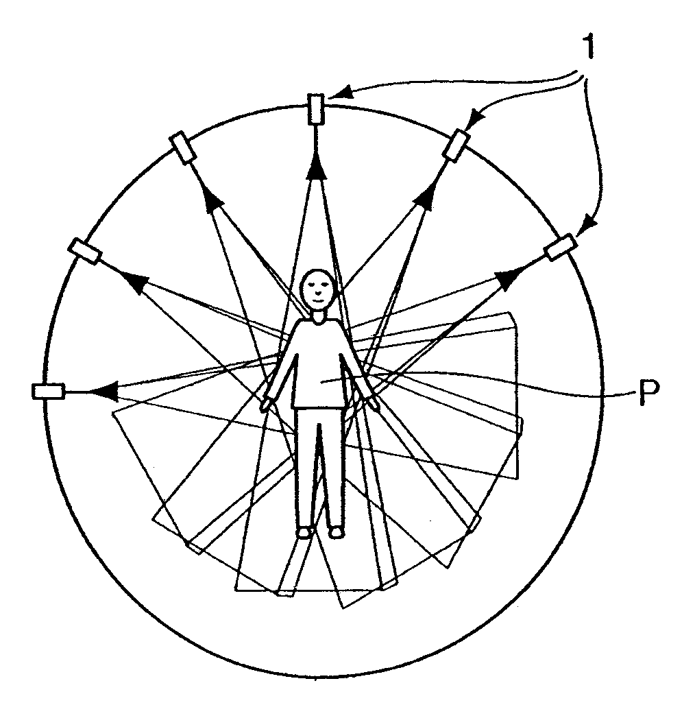
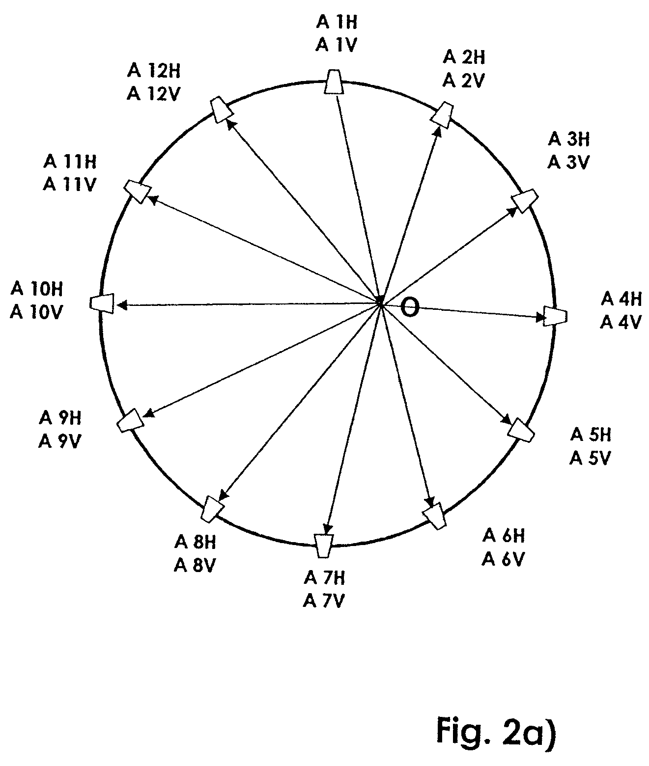
The invention is a method and device for detecting and analyzing objects using microwaves. The method involves arranging a plurality of microwave antenna units in a spatial pattern around the object to be detected, with each unit having two transmitting / receiving antennas with opposite polarizations. The microwaves are transmitted and received by the antennas, and the signals are analyzed to determine the object's material and location. The device includes a control unit to activate the microwave antenna units in a temporal sequence, an HF generator unit for providing power, and a collection unit for analyzing the microwave signals. The invention provides a more accurate and reliable method for detecting and analyzing objects with microwaves, with improved information density and reduced cost.

Problems solved by technology

Unfortunately, the resolution capability of a conventional microwave method is limited by its relatively long wavelength, but this drawback may be overcome by the use of tomographic measurement and reconstruction principles, which also enable objects to be reconstructed with a spatial resolution that under certain circumstances may even extend beyond the wavelength boundary.
However, apparatuses of this kind are extremely complex in mechanical terms, and expensive to build.
In addition, the object must remain motionless during the screening, a condition that is practically impossible, or at least very difficult to achieve, particularly when people are being examined.

Method used


Image

  • Method and device for the spatially resolved detection and reconstruction of objects by means of microwaves
  • Method and device for the spatially resolved detection and reconstruction of objects by means of microwaves
  • Method and device for the spatially resolved detection and reconstruction of objects by means of microwaves

Examples


Embodiment Construction

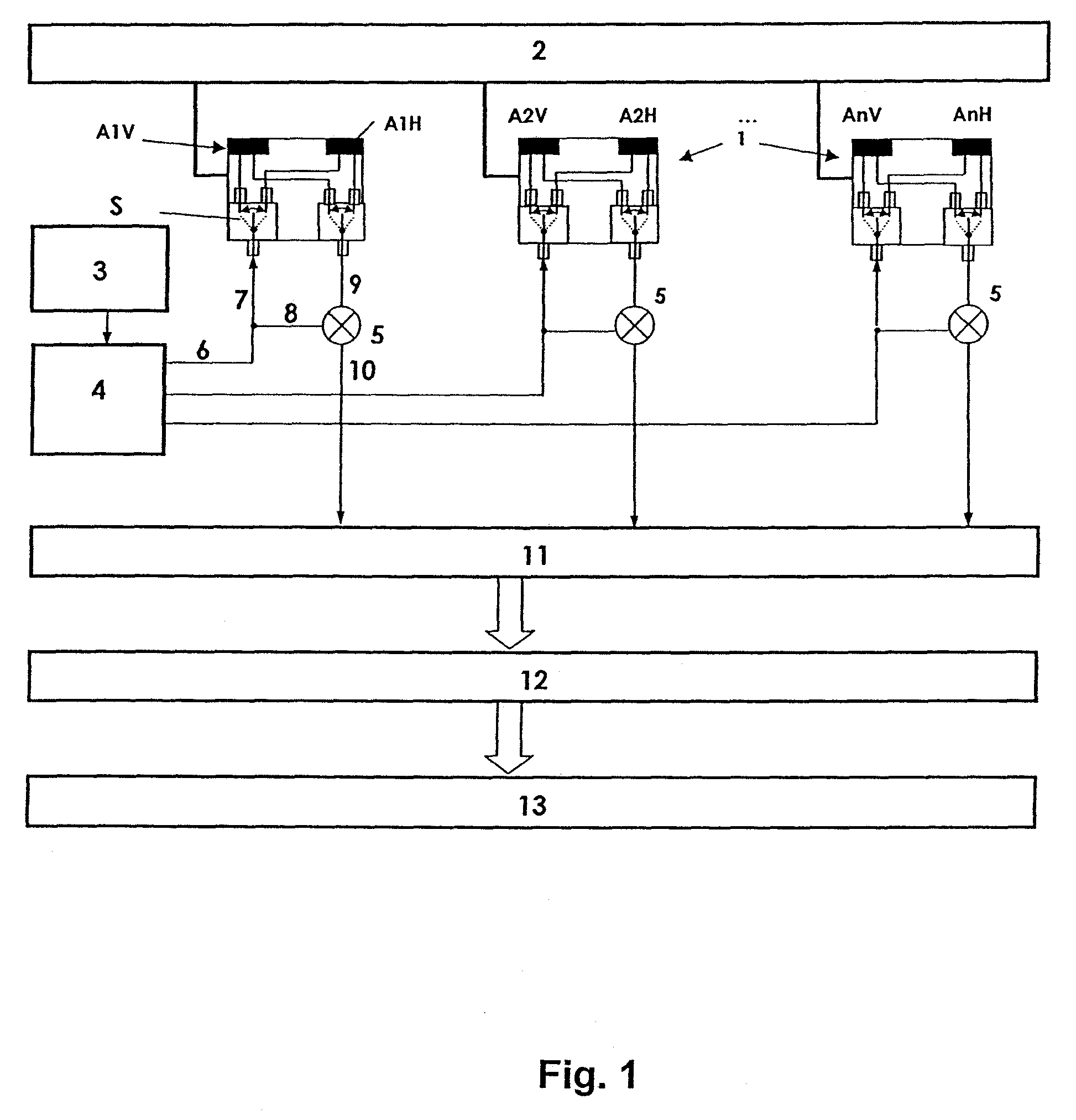
[0030]FIG. 1 shows one possible configuration of an embodiment of a microwave antenna unit that enables improved object capture and detection. The embodiment is based on a novel measurement approach using a sequentially actuated transmitter array with a distributed aperture in combination with switching individual antennas to enable time signals to be measured more quickly and more accurately, and special signal processing and image reconstruction technique.

[0031]The microwave antenna arrangement essentially has the following modules:

[0032]A plurality n of individual microwave antenna units 1, each having two transmitter / receiver antennas. The two antennas have opposite polarization to each other which is preferably a horizontal and a vertical polarization. In the following, reference characters AiH and AiV where i=1 . . . n will be used. A control unit 2 assures temporal control and switching of the individual antennas AiV, AiH from transmit to receive mode. Switches S are provided...


PUM


Abstract

A method and a device for the spatially resolved detection and reconstruction of objects using microwaves is described, in which at least one object to be detected is subjected to microwaves that are generated by a plurality of microwave antennas and microwave fractions reflected by the object are detected and converted into microwave signals that can be analyzed, based on which an analysis for the spatially resolved object detection is carried out.

Description

BACKGROUND OF THE INVENTION[0001]1. Field of the Invention[0002]The invention relates to a method and a device for the spatially resolved detection and reconstruction of objects by means of microwaves. In this context, at least one object to be detected is subjected to microwaves that are generated by a plurality of microwave antennas and at least fractions thereof are reflected by the object. These reflected microwave fractions are detected and converted into microwave signals that can be analyzed, based on which analysis for the spatially resolved object detection is carried out. An analysis technique of this kind is very suitable for security examinations, for example of people at border crossings. For example, it is possible to use this microwave technique to screen persons for hidden objects such as weapons, explosives and other such materials.[0003]2. Description of the Prior Art[0004]In today's globally interconnected world, security considerations are becoming more and more ...

Claims


Application Information

Patent Timeline
Patent Type & Authority Patents(United States)
IPC IPC(8): G01S13/00
CPCG01S7/025G01S13/887G01S13/89
Inventor KRONING, MICHAELBULAVINOV, ANDREYPINCHUK, ROMAN
Owner FRAUNHOFER GESELLSCHAFT ZUR FOERDERUNG DER ANGEWANDTEN FORSCHUNG EV
Learn More