
Remote monitor/control for billboard lighting or standby power system

a technology for monitoring/control and billboards, applied in the direction of transmission monitoring, data switching networks, instruments, etc., can solve the problems of reducing the effectiveness of billboards, and reducing false alarms, so as to improve performance and predictability, reduce false alarms, and easy to chang

Inactive Publication Date: 2012-08-21
COMMTIVA TECH
View PDF25 Cites 59 Cited by
  • Summary
  • Abstract
  • Description
  • Claims
  • Application Information

AI Technical Summary

Benefits of technology

"The present invention provides a system for remotely monitoring and controlling a remote operating system, such as a billboard lighting network, using wireless RF and / or the Internet. The system allows for flexible and customizable lighting schedules, as well as monitoring of individual bulb and ballast performance data to improve reliability and reduce energy costs. The system also allows for multiple on / off times for billboard lights to reduce energy costs and extend bulb lifetime. Additionally, the invention provides a power backup monitoring and control arrangement that can detect and communicate failures in the backup power supply system. The invention also utilizes cellular telephone networks to format SMS messages for increased efficiency and reduces communication costs."

Problems solved by technology

Thus, the loss of one or more lights of either of these types of displays renders it more difficult, and perhaps even impossible, to discern the displayed message.
A billboard lighting failure thus reduces billboard effectiveness in carrying out its intended purpose.
Because of the remote location of many billboards, this type of failure may go undetected for an extended period before it is corrected.

Method used


Image

  • Remote monitor/control for billboard lighting or standby power system
  • Remote monitor/control for billboard lighting or standby power system
  • Remote monitor/control for billboard lighting or standby power system

Examples


Embodiment Construction

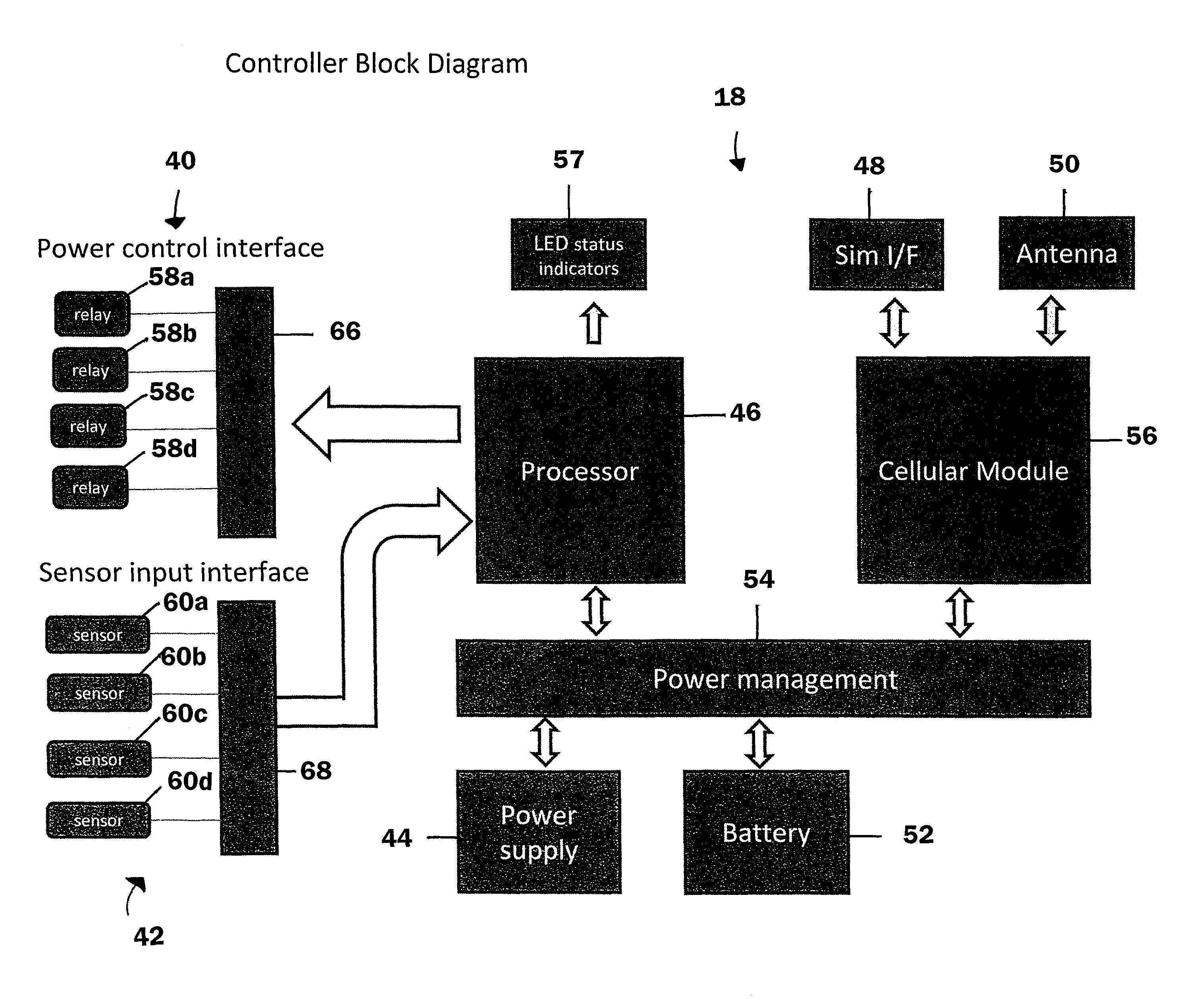
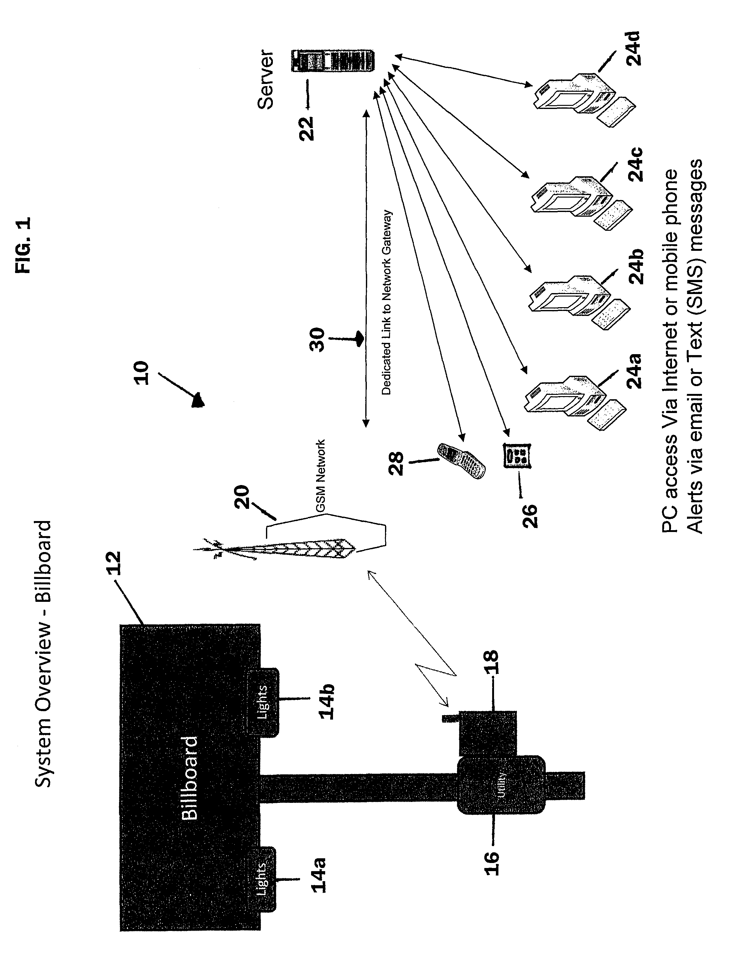
[0030]Referring to FIG. 1, there is shown a simplified block and schematic diagram of a remote monitor / control system 10 for use with billboard lighting in accordance with one embodiment of the present invention. Remote monitor / control system 10 is adapted for use with a billboard 12 having a first set of lights 14a on one side and a second set of lights 14b on the second, opposed side of the billboard. A utility power connection 16 provides electric power to lights 14a and 14b. Lights 14a and 14b illuminate opposed sides of billboard 12 upon which are displayed messages in graphic form. However, a billboard 12 used in the present invention may have any number of faces with each face illuminated by virtually any number of lights. The system described herein is designed to accommodate as many as four (4) faces in the billboard illuminated by as many as twenty-four (24) lights.

[0031]Also connected to lights 14a and 14b is a remote monitor / controller 18 which monitors and controls the ...


PUM


Abstract

A lighting monitor / control system for remote billboards uses a cellular network to provide utility power and light status information to a central controller, which in response provides control signals to individual remote billboard lighting controllers for setting operating parameters such as multiple on / off times, lighting power adjustments for individual billboards, and custom lighting schedules based upon geographic and environmental considerations. Battery back-up is provided in the event of utility power outage with automatic reversion to utility power when restored. Immediate notification of failure of utility power or of individual lamp or ballast failure is provided by SMS messaging formatted so as to minimize the number of messages and reduce communications costs. The monitor / control system is also adapted for use in remote power monitoring applications to automatically switch to standby power (generator) in the absence of primary power and to return to primary power when restored.

Description

FIELD OF THE INVENTION[0001]This invention relates generally to the remote monitoring / control of an operating system, and is particularly directed to an arrangement for the monitor / control of remote billboard lighting or standby electrical power systems.BACKGROUND OF THE INVENTION[0002]Display signs are used in a wide variety of industries, and are frequently used in the promotion and advertising of products and services. Some of these display signs are used indoors, while others are used in an outdoor environment. One popular outdoor display sign is the billboard, which is typically located in populous or high-traveled areas, such as, for example, along roadsides or on the exterior of buildings. The traditional billboard is a “static” type of display sign in that the advertising image is permanently or semi-permanently affixed to the boards as paint or paper applied in the form of the message to be conveyed. In order to provide 24-hour viewing of the billboard display, an array of ...

Claims


Application Information

Patent Timeline
Patent Type & Authority Patents(United States)
IPC IPC(8): H04B7/00
CPCG06F3/147H04L12/40013G09G2330/021G09G2360/144G09G2370/16G09G2380/06
Inventor HANWRIGHT, MARTIN JAMESCHEN, SHIH-CHIEA
Owner COMMTIVA TECH
Learn More