
Remote optothermal sensor (ROSE) standoff detection of CWAs, explosives vapors and TICs

a technology of optothermal sensor and remote optothermal sensor, which is applied in the direction of optical radiation measurement, instruments, and investigating moving fluids/granular solids, etc., can solve the problems of difficult problem, significant additional obstacles, and less than satisfactory traditional light detection and ranging (lidar) and differential absorption lidar measurement schemes

Active Publication Date: 2012-08-21
DAYLIGHT SOLUTIONS
View PDF4 Cites 11 Cited by
  • Summary
  • Abstract
  • Description
  • Claims
  • Application Information

AI Technical Summary

Benefits of technology

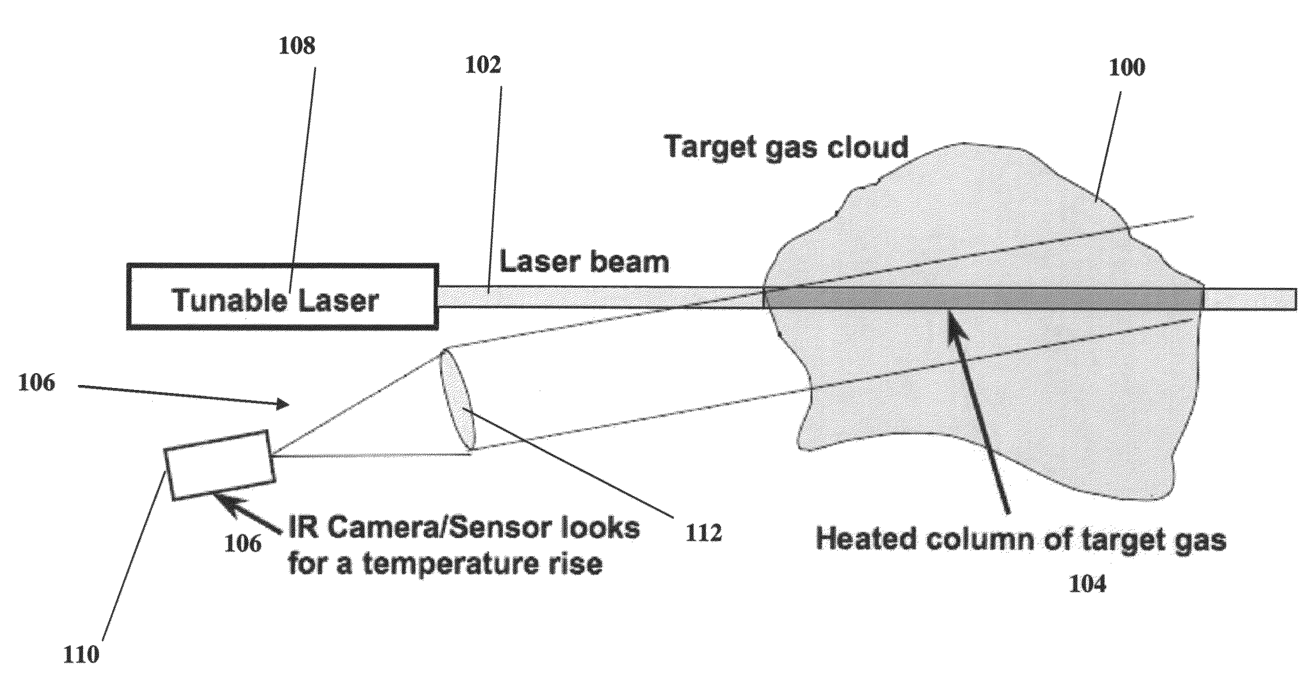
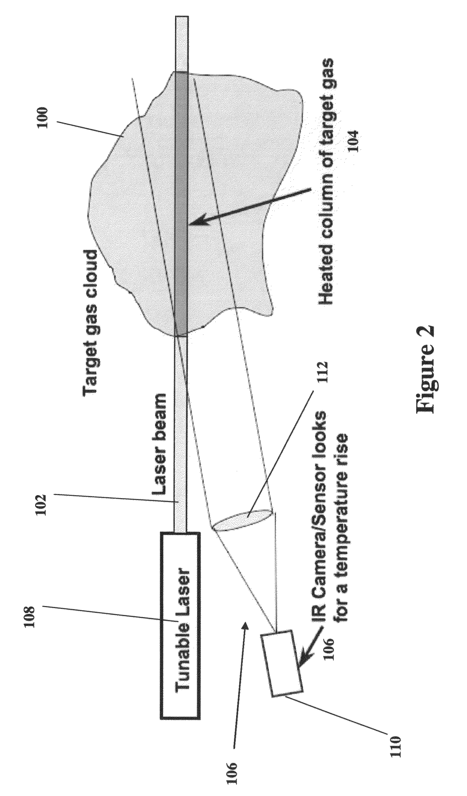
The present invention provides a new method and system for detecting gases at long distances using optical response. This new gas detector has many advantages of previous detectors and is not anticipated, suggested, or implied by any of them. The technology involves using photothermal spectroscopy at a distance rather than photoacoustic spectroscopy in a point sensor local to the sample. The invention can detect hazardous or weapon gases by detection of optical response at a distance. The system uses a laser tuned to a first wavelength for a first gas and a heat sensor to detect heat generated by the gas absorbing the first wavelength. The method includes providing a source of illumination capable of transmitting a plurality of wavelengths and illuminating the gas cloud with only one illuminating wavelength at a time. The optical response of the gas cloud to each illuminating wavelength is determined resulting in the determination of the constituents of the gas cloud by resolving a mole fraction for each constituent.

Problems solved by technology

For single-ended standoff detection applications, traditional light detection and ranging (LIDAR) and differential absorption LIDAR (DIAL) measurement schemes are less than satisfactory because of the small Raman scattering signal returns (for LIDAR) and small Rayleigh scattering returns (for DIAL) from molecular clouds containing explosives vapors and CWAs, especially when the target gasses are present at low concentrations.
However, for a single-ended detection scheme, the problem is significantly harder and provides significant additional obstacles.

Method used


Image

  • Remote optothermal sensor (ROSE) standoff detection of CWAs, explosives vapors and TICs
  • Remote optothermal sensor (ROSE) standoff detection of CWAs, explosives vapors and TICs
  • Remote optothermal sensor (ROSE) standoff detection of CWAs, explosives vapors and TICs

Examples


Embodiment Construction

)

[0034]The detailed description set forth below in connection with the appended drawings is intended as a description of presently-preferred embodiments of the invention and is not intended to represent the only forms in which the present invention may be constructed and / or utilized. The description sets forth the functions and the sequence of steps for constructing and operating the invention in connection with the illustrated embodiments. However, it is to be understood that the same or equivalent functions and sequences may be accomplished by different embodiments that are also intended to be encompassed within the spirit and scope of the invention.

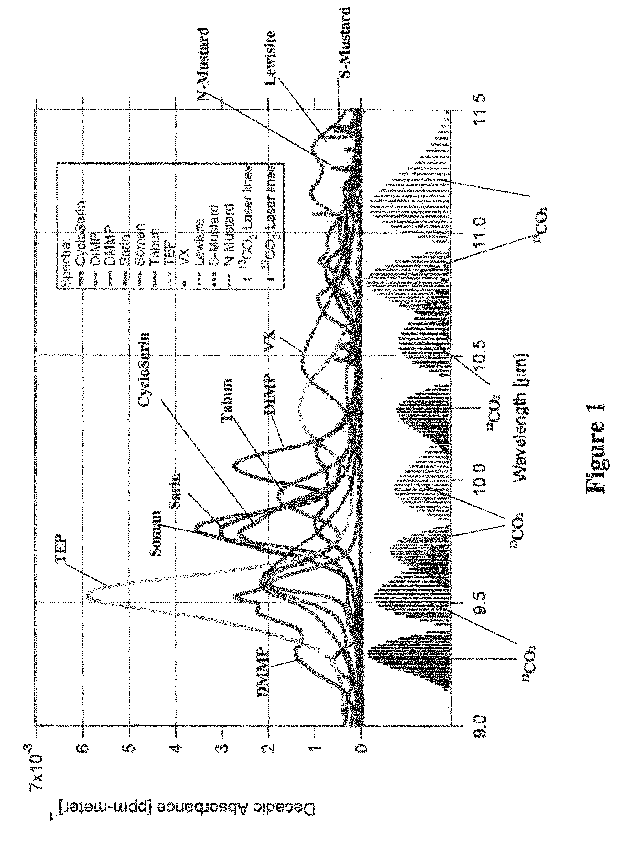
[0035]The present invention resides in a novel system and method for standoff detection of explosives, CWAs and TICs using optical techniques. Preliminary analysis indicates that TNT can be detected at a distance of 0.5 km with a signal-to-noise ration exceeding 10,000. Optical techniques may permit unambiguous detection of target mole...


PUM


Abstract

A system and method for standoff detection of explosives, CWAs and TICs using optical techniques. Preliminary analysis indicates detection of TNT at a distance of 0.5 km with a signal-to-noise ratio exceeding 10,000. The optical / thermal techniques apparently permit unambiguous detection of the target molecules even the presence of commonly encountered interferents. The technique, named Remote Optothermal Sensor (ROSE), has the potential for standoff detection at distances greater than one (1) kilometer.

Description

COPYRIGHT AUTHORIZATION[0001]A portion of the disclosure of this patent document contains material which is subject to copyright and / or mask work protection. The copyright and / or mask work owner has no objection to the facsimile reproduction by anyone of the patent document or the patent disclosure, as it appears in the Patent and Trademark Office patent file or records, but otherwise reserves all copyright and / or mask work rights whatsoever.BACKGROUND OF THE INVENTION[0002]1. Field of the Invention[0003]This invention relates to the detection of gasses at long distance and more particularly the detection of hazardous or chemical weapon gasses by detection of optical response.[0004]2. Description of the Related Art[0005]Chemical warfare agents (CWAs), explosives vapors and many toxic industrial chemicals (TICs) absorb radiation in the medium wave infrared (MWIR) and long wave infrared (LWIR) region. This is the basis of high sensitivity, high selectivity low probability of false ala...

Claims


Application Information

Patent Timeline
Patent Type & Authority Patents(United States)
IPC IPC(8): G01J5/02
CPCG01N33/0057G01N21/39G01N21/71G01N2021/1793
Inventor PATEL, C KUMAR NMUKHERJEE, ANADI
Owner DAYLIGHT SOLUTIONS
Learn More