
Method for manufacturing semiconductor device

a semiconductor and manufacturing method technology, applied in the field of semiconductor technology, can solve the problems of reducing the signal-to-noise ratio, reducing the gate threshold voltage, deteriorating the electrical properties of the device, etc., and achieves the effect of increasing the distance, increasing the distance, and reducing the parasitic capacitan

Active Publication Date: 2012-08-21
INST OF MICROELECTRONICS CHINESE ACAD OF SCI
View PDF8 Cites 2 Cited by
  • Summary
  • Abstract
  • Description
  • Claims
  • Application Information

AI Technical Summary

Benefits of technology

[0010]To solve the above problem, the present invention provides a method for manufacturing a semiconductor device which facilitates alleviation of short channel effects, and decreasing an electrical resistance between source / drain regions and a parasitic capacitance.
[0015]Compared with the conventional technology, the technical solution according to the present invention has the following beneficial effects.
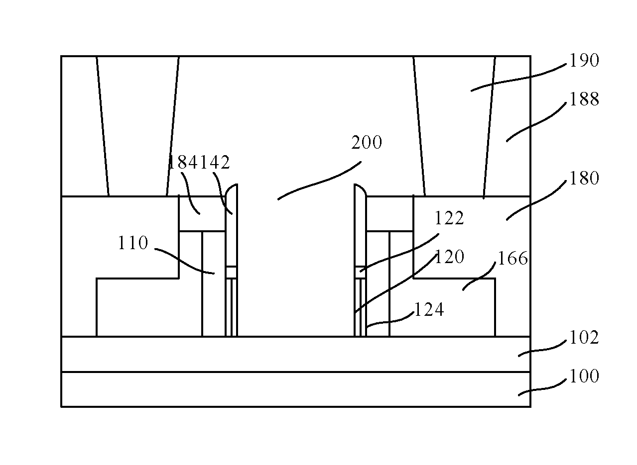
[0016]In a semiconductor substrate including a channel region having the same thickness as that in the conventional technology, a cavity is formed in the semiconductor substrate so as to increase a distance between the respective gates at the second sidewall of the semiconductor substrate, and further increase a distance between the gate and the source / drain regions, which facilities decrease of a parasitic capacitance. Moreover, due to the existence of the cavity, source / drain regions adjacent to the semiconductor substrate have an increased lateral area, compared with the conventional technology and assuming that the semiconductor substrate has the same height, because the source / drain regions have an increased width, which facilitates decrease of an electrical resistance between the source / drain regions. Furthermore, due to the existence of the cavity, an isolating region is provided between the source / drain regions, which facilitates reduction of short channel effects.
[0017]By providing the sacrificial layer on the semiconductor layer on the first insulating layer, and the first and second sidewall spacers around the sacrificial layer, the semiconductor substrate can be processed in a self-aligned manner with the first and second sidewall spacers as a hard mask, which decreases the number of the masks to be used and simplifies the manufacturing process.
[0018]By filling the cavity with the third dielectric layer, a possibility of introducing contamination in the cavity is minimized.

Problems solved by technology

The short channel effect deteriorates electrical properties of the device, which, for example, leads to a reduced gate threshold voltage, increased power consumption, and a lowered signal-to-noise ratio.
To suppress the short channel effect, the channel has to be doped with more elements such as phosphorus, boron, and the like, which, however, decreases the carrier mobility in the channel of the device.
Moreover, it is difficult to provide a steep doping profile in the channel, which in turn leads to a severe short channel effect.
Furthermore, conventional strained silicon technology in SiGe PMOS encounters a bottleneck and may not apply larger stress to the channel.
Furthermore, there also exists a bottleneck for the thickness of the gate oxide dielectric layer, and thinning of the gate oxide may not follow the decreasing of the gate length.
With continuous decrease of the feature size, the resistance for the source / drain regions will increase and the power consumption of the device will become larger.
However, it is required that the silicon layer in the channel have an extremely small thickness for a fully depleted device.
The conventional manufacturing process, especially the conventional manufacturing process on the basis of bulk silicon, is difficult to provide a semiconductor structure as required, or has a high manufacturing cost.
Even for an emerging SOI (silicon-on-insulator) process, it is still difficult for a silicon layer in the channel to have a small thickness.

Method used


Image

  • Method for manufacturing semiconductor device
  • Method for manufacturing semiconductor device
  • Method for manufacturing semiconductor device

Examples


Embodiment Construction

[0039]The disclosure below provides various embodiments or examples for carrying out the technical solution of the present invention. Although the components and arrangements of some specific examples are described, they are only examples, and are not construed as limiting the present invention.

[0040]Moreover, reference numerals and / or letters are repeated in various embodiments. The repetition is for simplicity and clarity, and does not represent relationship between various embodiments and / or settings to be discussed below.

[0041]Various specific processes and / or materials are used in the present invention. Nevertheless, one skilled person in the art will appreciate that other processes and / or materials can also be used as alternatives without departing from the protection scope of the invention. It should be noted that boundaries of various regions described herein include necessary extensions introduced by the process.

[0042]According to the present invention, there is provided a ...


PUM


Abstract

The present application discloses a method for manufacturing a semiconductor device, comprising the steps of: forming a semiconductor substrate, a gate stack and a second protection layer in sequence on a first insulating layer; after defining a gate region and removing portions of the second protection layer and the gate stack outside the gate region, while keeping portions of the stop layer, the semiconductor layer and the second insulating layer which covers sidewalls of the patterned semiconductor layer outside the gate region and exposing the sacrificial layer, performing source / drain ion implementation in the semiconductor layer; after forming a second sidewall spacer so as to cover at least the exposed portion of the sacrificial layer, removing the first protection layer and the second protection layer so as to expose the semiconductor layer and the gate stack; and forming a contact layer on the exposed portion of the semiconductor layer and the gate stack; performing planarization so as to expose the first protection layer, and then removing the first protection layer, the sacrificial layer, the stop layer and the semiconductor layer with the first sidewall spacer and the second sidewall spacer as a mask, so as to form a cavity which exposes the first insulating layer. It facilitates reduction of short channel effects, resistance of source / drain regions, and parasite capacitance.

Description

CROSS-REFERENCE TO RELATED APPLICATION(S)[0001]This application is a National Phase application of, and claims priority to, PCT Application No. PCT / CN2011 / 071488, filed on Mar. 3, 2011, entitled “Method for Manufacturing Semiconductor Device”, which claims priority to Chinese Application No. CN 201010617419.3, filed on Dec. 31, 2010. Both the PCT Application and Chinese Application are incorporated herein by reference in their entireties.FIELD OF THE INVENTION[0002]The present invention relates to semiconductor technology, and particularly, to a method for manufacturing a semiconductor device.BACKGROUND OF THE INVENTION[0003]When the channel length of a metal oxide semiconductor field effect transistor (MOSFET) becomes smaller continuously, many negligible effects in the long-channel model of the MOSFET becomes more significant, and has even been a dominant factor determining its properties. These effects are commonly referred to as short channel effects. The short channel effect de...

Claims


Application Information

Patent Timeline
Patent Type & Authority Patents(United States)
IPC IPC(8): H01L21/336
CPCH01L29/66795
Inventor ZHU, HUILONGLI, CHUNLONGLUO, JUN
Owner INST OF MICROELECTRONICS CHINESE ACAD OF SCI
Learn More