
Loader work apparatus

a technology for working equipment and loaders, which is applied in the direction of cranes, lifting devices, constructions, etc., can solve the problems of increasing the width of the vehicle, affecting the commercial value, and hindering the driver's view to the front side of the vehicle body

Active Publication Date: 2012-08-21
KUBOTA LTD
View PDF12 Cites 6 Cited by
  • Summary
  • Abstract
  • Description
  • Claims
  • Application Information

AI Technical Summary

Benefits of technology

[0009]In view of the above, the object of the present invention is to provide a loader work apparatus which allows a hydraulic hose to be disposed without the hose extending on the inner or outer side of the mast, the hydraulic hose constituting a piping system extending from a control valve mounted on the vehicle body to a hydraulic actuator for an attachment to be mounted to the boom.
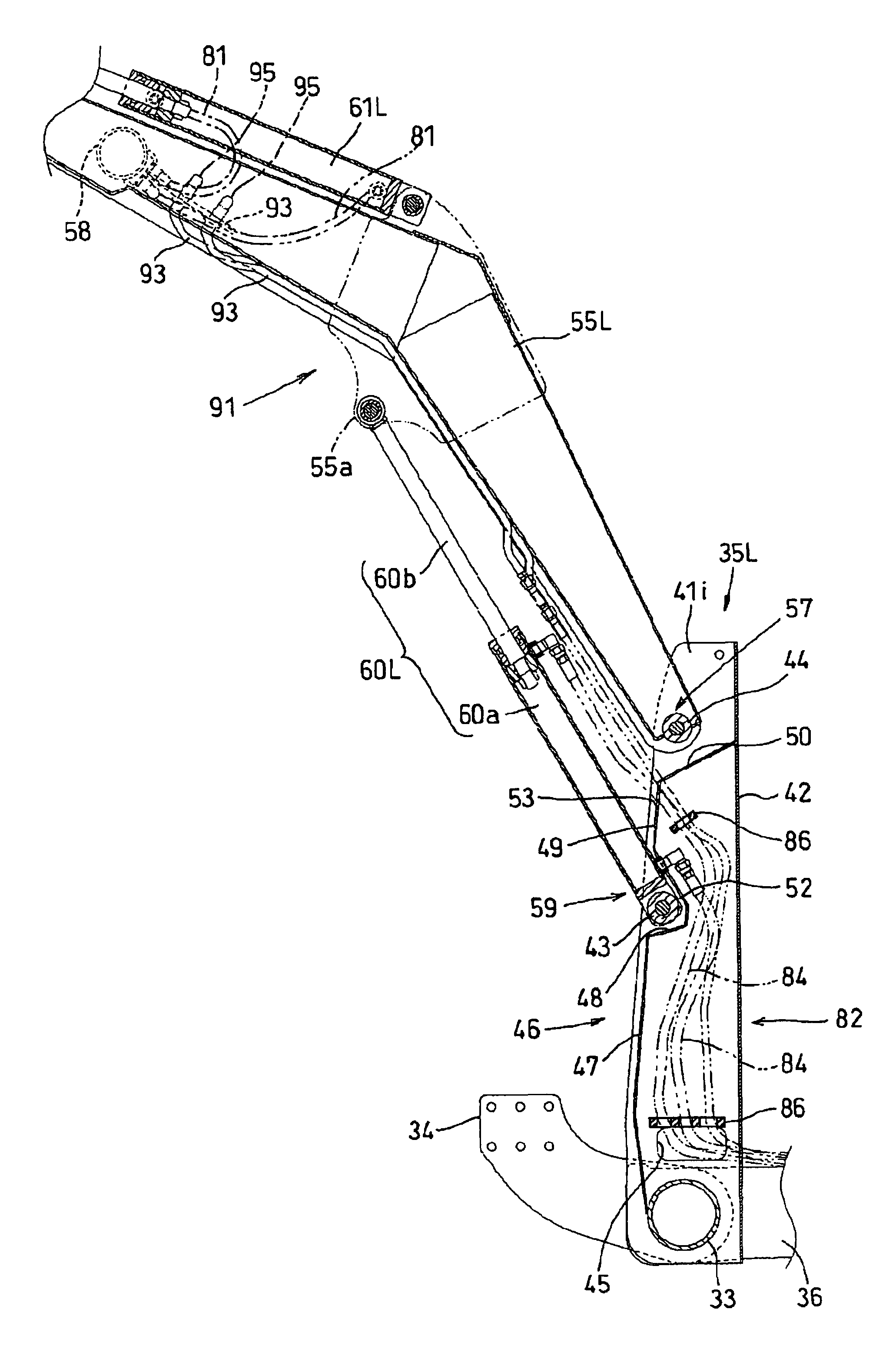
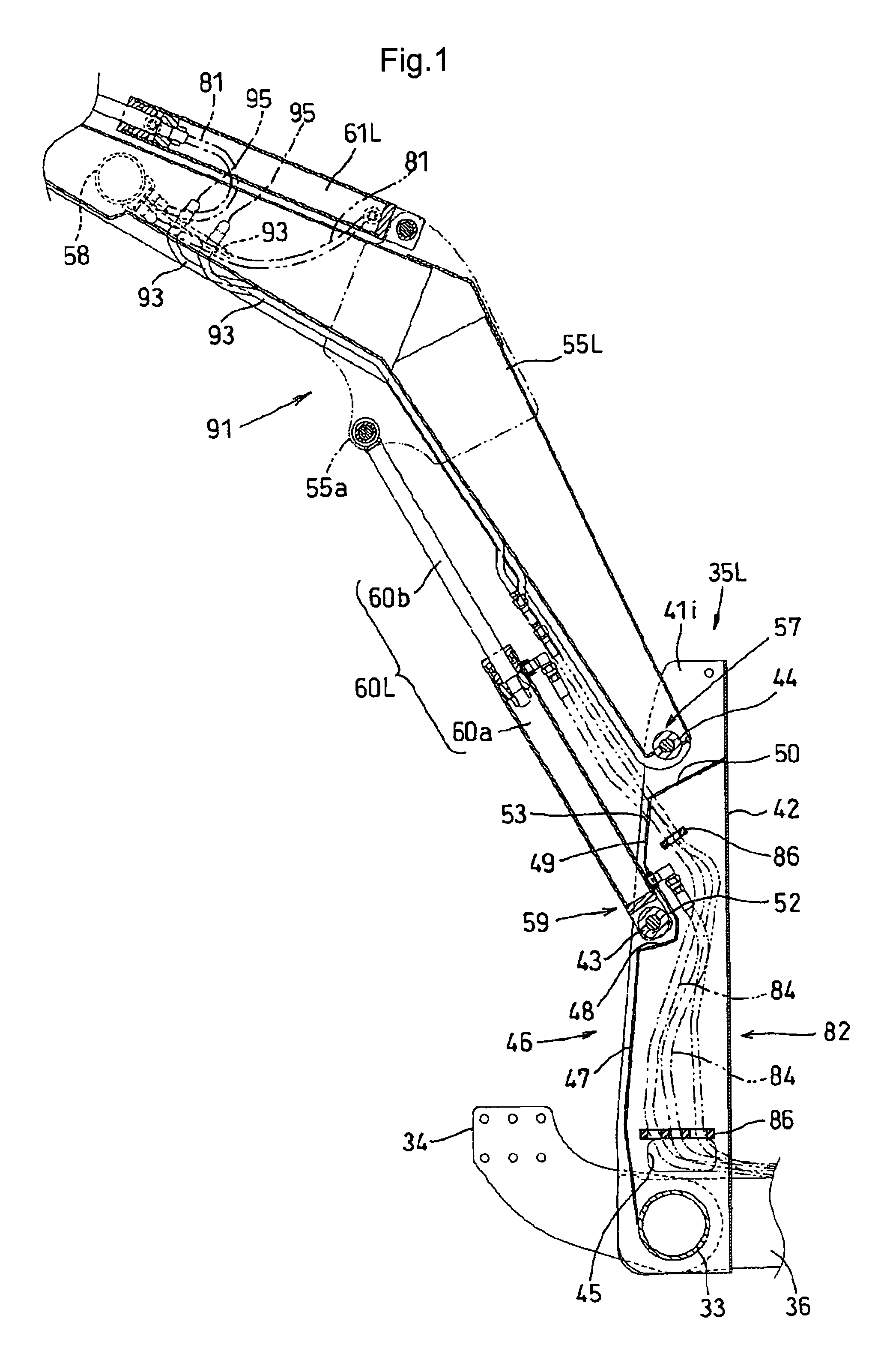
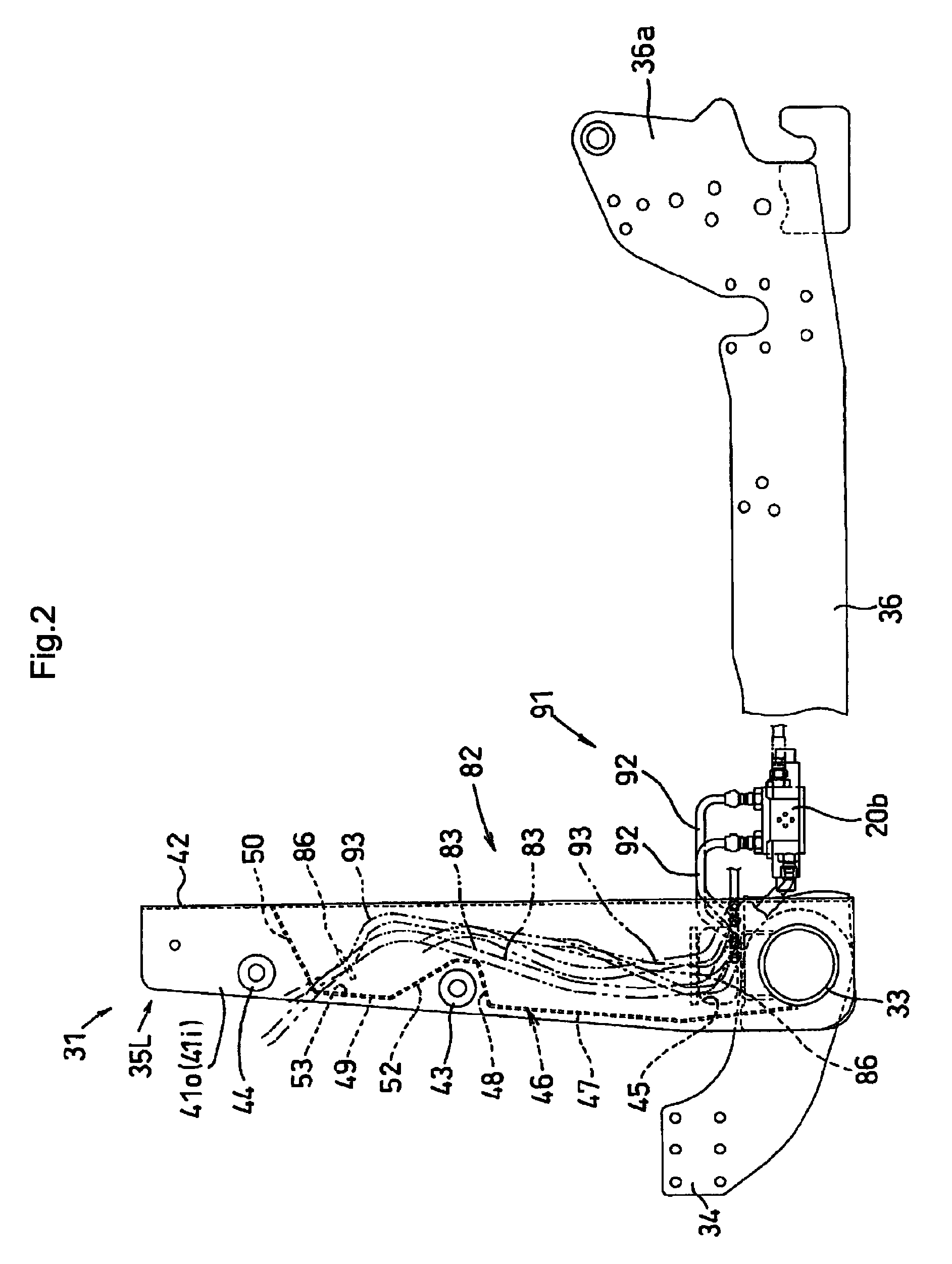
[0019]With the above-described construction, the channel constituting member extending from the control valve is disposed through the inside of the mast to the loader. Therefore, there is eliminated the risk of this channel constituting member hindering the driver's front side view. Further, as this channel constituting member is protected within the mast, there is also no risk of the member being damaged through its collision with an obstacle or the like present on a lateral side of the vehicle body. Still further, as the channel constituting member is hidden inside the mast, the appearance of the entire loader work machine will be improved also.
[0021]With the above, the cylinder tube whose length is invariable regardless of pivotal movements of the boom is pivotally supported to the mast and the channel constituting member is connected to this cylinder tube. Therefore, even with the expansion / contraction of the piston rod associated with pivotal movement of the boom, there will hardly occur displacement (back and forth movement) in the piston rod, of a joint between this channel constituting member and the cylinder tube. Therefore, the channel constituting member only needs such an amount of play which allows the member to follow the pivotal movement of the hydraulic cylinder. With this, the channel constituting member can be formed short and compact.
[0023]With the above, the hydraulic cylinder for pivoting the boom and the boom are disposed with one being upwardly of the other, thus allowing effective utilization of a dead space formed between the hydraulic cylinder and the boom.
[0036]With the above-described construction, the channel constituting member extending from the control valve is disposed through the inside of the mast to the loader. Therefore, there is eliminated the risk of this channel constituting member hindering the driver's front side view. Further, as this channel constituting member is protected within the mast, there is also no risk of the member being damaged through its collision with an obstacle or the like present on a lateral side of the vehicle body. Still further, as the channel constituting member is hidden inside the mast, the appearance of the entire loader work machine will be improved also.
[0043]Further, the insides of the masts disposed on the right and left sides of the vehicle body can be effectively utilized as piping arranging space.

Problems solved by technology

However, if this hydraulic hose is exposed on the inner side of the mast, this will not only impair the commercial value, but also hinder the driver's view to the front side of the vehicle body.
On the other hand, if the hydraulic hose is exposed on the outer side of the mast, this may result in not only increase in the vehicle width, but also premature damage of the hydraulic hose due to impact or friction thereof to e.g. an obstacle present on a lateral side of the vehicle body.
Hence, such arrangements are undesirable.

Method used


Image

  • Loader work apparatus
  • Loader work apparatus
  • Loader work apparatus

Examples


further embodiment

[0125]A further embodiment of the present invention will be described with reference to the accompanying drawings.

[0126]In FIGS. 10 and 11, numeral 101 denotes a work vehicle commonly called TLB (tractor-loader-backhoe) including a tractor 102, a front loader 103 attachable to a front portion of the tractor 102 and a backhoe 104 attachable to a rear portion of the tractor 102.

[0127]A vehicle body 2A of the tractor 102 mounts an engine, a clutch housing 109 connected to a rear portion of the engine via e.g. a flywheel housing and a transmission case 110 connected to a rear portion of the clutch housing 109 and the vehicle body can travel by means of a pair of right and left front wheels 107 and a pair of right and left rear wheels 108.

[0128]To a front lower portion of the engine, there are fixedly attached, via fasteners such as bolts, a pair of right and left front axle frames 111 extending forwardly from the engine. Upon the front axle frames 111, there are mounted such vehicle com...


PUM


Abstract

A work apparatus to be mounted to a work vehicle includes: a pair of cylindrical masts 35 disposed erect on right and left sides of a vehicle body having a control valve; a boom 91 pivotally supported to the masts; an implement pivotally supported to the boom; a boom cylinder 60 for pivoting the boom; an implement cylinder 61 for operating the implement; a boom piping system communicating the control valve with the boom cylinder; and an implement piping system communicating the control valve with the implement cylinder; wherein a channel constituting member 84 constituting the boom piping system extends vertically within each mast; one end of the channel constituting member 84 extends to the outside at a lower portion of the mast to be connected with the control valve; and the other end of the channel constituting member 84 extends to the outside at an upper portion of the mast 35 to be connected with boom cylinder 60.

Description

BACKGROUND OF THE INVENTION[0001]1. Field of the Invention[0002]The present invention relates to a loader work apparatus to be mounted to a work vehicle such as a tractor.[0003]2. Description of Related Art[0004]There is known a loader work machine having a pair of masts projecting upward on right and left sides of a body of a tractor and a loader mounted to upper portions of the masts, the loader having a bucket and a boom.[0005]With this loader work machine, the boom of the loader has its base end pivotally supported to the mast and this boom is vertically pivotable by a boom cylinder interposed between the boom and the mast. Further, at a leading end of the boom, there are disposed a bucket and a bucket cylinder, so that in association with an expanding or contracting movement of the bucket cylinder the bucket effects a scooping or dumping operation. Further, a control valve is attached to the mast for controlling a supply amount of pressure oil to be supplied to the boom cylinde...

Claims


Application Information

Patent Timeline
IPC IPC(8): E02F3/36
CPCE02F3/382E02F3/627
Inventor FUKUDOME, HIROKITAKAGI, MASATAKASAITO, KOJIMIYAZAKI, EIJITAKESHITA, SHUICHI
Owner KUBOTA LTD
Learn More