Method and arrangement for controlling an electrical device

a technology for controlling an electrical device and an electrical device, which is applied in emergency power supply arrangements, instruments, transportation and packaging, etc., can solve the problems of cumbersome and inconvenient use of electrical devices, 100-300 mw power loss, and undesirable waste of energy, so as to reduce the power consumption of the first electrical device and reduce the effect of power consumption

Active Publication Date: 2012-08-14
SALCOMP OYJ
View PDF6 Cites 5 Cited by
  • Summary
  • Abstract
  • Description
  • Claims
  • Application Information

AI Technical Summary

Benefits of technology

[0017]a control circuitry arranged to reduce power consumption of the first electrical device as a response to a situation in which the change of the electrical quantity associated with the resistor is indicative of a decrease of power dissipated in the resistor.
[0018]In accordance with a second aspect of the invention a novel method for detecting a situation in which a first electrical device is connected to a second electrical device is provided. The method comprises detecting the situation in which the first electrical device is connected to the second electrical device on the basis of a change of an electrical quantity associated with the resistor connected between the first electrical contact terminal and the second electrical contact terminal, and the method further comprises reducing the power consumption of the first electrical device as a response to a situation in which the change of the electrical quantity associated with the resistor is indicative of a decrease of power dissipated in the resistor.
[0020]The voltage between the second electrical contact terminal and the third electrical contact terminal can be selected to be so low that power losses in the first electrical device can be low in a state in which the first electrical device is not connected to the second electrical device. Therefore, undesirable waste of energy can be reduced compared with the prior art solution described earlier in this document.
[0028]a control circuitry arranged to reduce power consumption of the electronic device as a response to a situation in which the change of the electrical quantity associated with the resistor is indicative of a decrease of power dissipated in the resistor.

Problems solved by technology

For example, in charger devices for mobile phones there is typically a 100-300 mW power loss in a situation in which a charger device is connected to a power grid but it is not connected to a mobile phone.
Therefore, keeping an electrical device in a full state of readiness may cause undesirable waste of energy.
The need to operate a switch or other control means makes, however, the usage of the electrical device more cumbersome and inconvenient.
Furthermore, a risk for erroneous use is increased.

Method used


Image

  • Method and arrangement for controlling an electrical device
  • Method and arrangement for controlling an electrical device
  • Method and arrangement for controlling an electrical device

Examples


Embodiment Construction

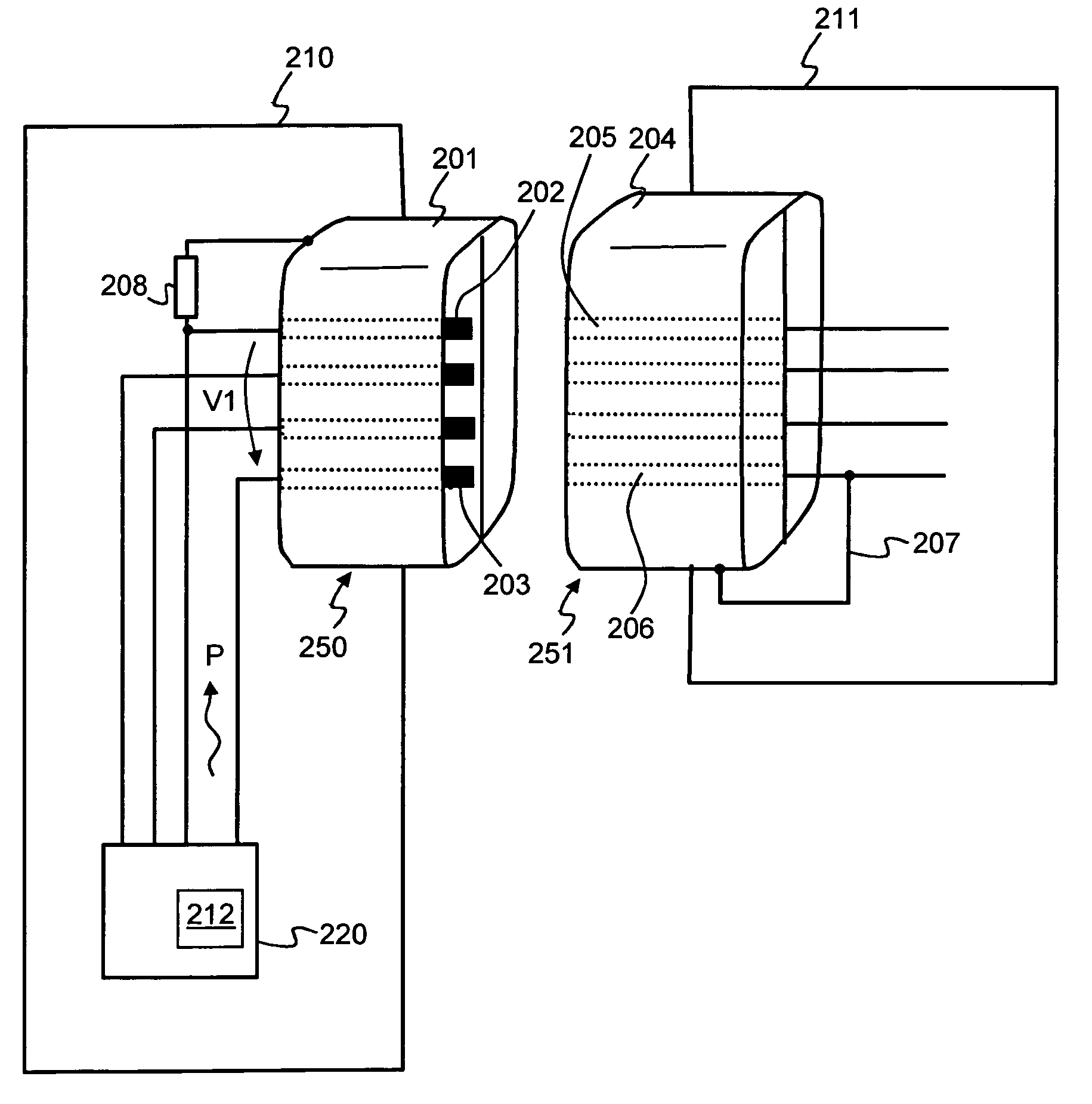
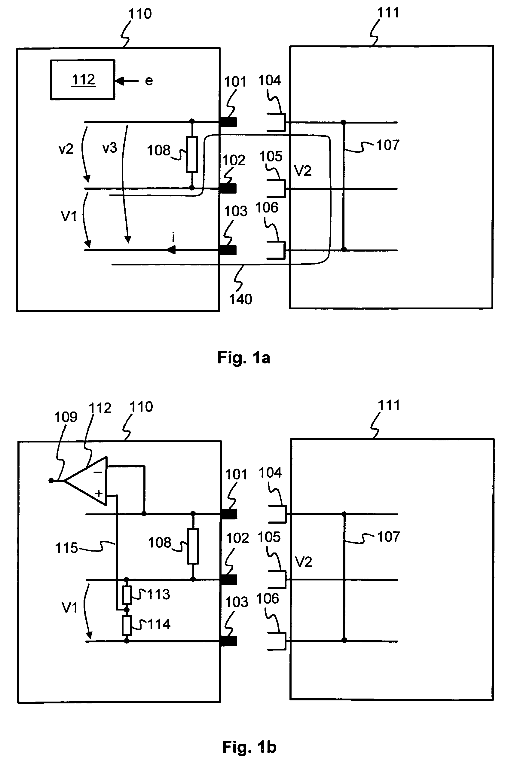
[0037]FIG. 1a shows an arrangement according to an embodiment of the invention for detecting a situation in which a first electrical device 110 is connected to a second electrical device 111. The electrical device 110 comprises a first electrical contact terminal 101, a second electrical contact terminal 102, and a third electrical contact terminal 103. The said electrical contact terminals can be, for example, electrical contact terminals, e.g. pins or contact strips, of an electrical connector. Non-zero voltage V1 is arranged to prevail between the electrical contact terminals 102 and 103. The electrical device 111 comprises a first counterpart 104 that is arranged to fit with the electrical contact terminal 101, a second counterpart 105 that is arranged to fit with the electrical contact terminal 102, and a third counterpart 106 that is arranged to fit with the electrical contact terminal 103. The electrical device 111 comprises a galvanic contact 107 between the counterpart 104 ...


PUM


Abstract

The invention relates to a method and arrangement for detecting a situation in which an electrical device is connected to another electrical device. The electrical device comprises a first, second, and third electrical contact terminal (101, 102, 103). Non-zero voltage is arranged between the second and third electrical contact terminal. The other electrical device comprises counterparts (104, 105, 106) for the first, second, and third electrical contact terminal. There is a galvanic coupling (107) between the counterparts for the first and second electrical contact terminal. The arrangement comprises a resistor (108) between the first and second electrical contact terminal and a detector (112) for detecting the situation in which the electrical device is connected to the other electrical device on the basis of a change of an electrical quantity associated with the resistor. The first electrical contact terminal can be e.g. a metal shield on a USB-connector.

Description

CROSS REFERENCE TO RELATED APPLICATION[0001]This application claims priority under 35 USC §119 to Finnish Patent Application No. 20070909 filed on Nov. 27, 2007.FIELD OF THE INVENTION[0002]The invention relates to a method and arrangement for detecting a situation in which an electrical device is connected to another electrical device. The invention relates also to an electrical device capable of detecting a situation in which the electrical device is connected to another electrical device.BACKGROUND OF THE INVENTION[0003]Many electrical devices are designed to operate in conjunction with other electrical devices. For example, a charger device is designed to supply a specified voltage and / or electrical current to a battery operated electrical device in order to charge batteries of the battery operated electrical device. The battery operated electrical device can be, for example, a mobile phone or a palmtop computer. As another example, a data collecting and analysing device is desig...

Claims


Application Information

Patent Timeline
Patent Type & Authority Patents(United States)
IPC IPC(8): H02J7/04H02J7/16
CPCG06F1/266H02J7/0045H02J2009/007H02J7/02H02J9/005H02J9/007G01R31/66H02J7/00
Inventor MINKKINEN, JARMO
Owner SALCOMP OYJ
Why Eureka
Try Eureka