
High-precision synchronization of pulsed gas-discharge lasers

a gas-discharge laser, high-precision technology, applied in the direction of laser details, electrical equipment, active medium materials, etc., can solve the problems of high and potentially destructive peak currents through the power supply, inability to be corrected, and the realization of such power supply is only technologically achievable with great difficulty and significant expens

Active Publication Date: 2012-08-07
COHERENT GMBH
View PDF7 Cites 23 Cited by
  • Summary
  • Abstract
  • Description
  • Claims
  • Application Information

AI Technical Summary

Benefits of technology

Achieves temporal stability of overlapped light pulses within nanosecond range, maintaining the complex temporal pulse-shape and energy requirements for applications like laser annealing without the need for improved power supplies or additional laser components.

Problems solved by technology

The higher impedance value is necessary to protect the power supply from energy reflected back from the laser discharge, which could otherwise cause very high and potentially destructive peak currents through the power supply.
This is a random pulse-to-pulse phenomenon and can not be predicted, and accordingly can not be corrected.
Realization of such power supplies, however, is technologically achievable only with great difficulty and at significant expense.

Method used


Image

  • High-precision synchronization of pulsed gas-discharge lasers
  • High-precision synchronization of pulsed gas-discharge lasers
  • High-precision synchronization of pulsed gas-discharge lasers

Examples


Embodiment Construction

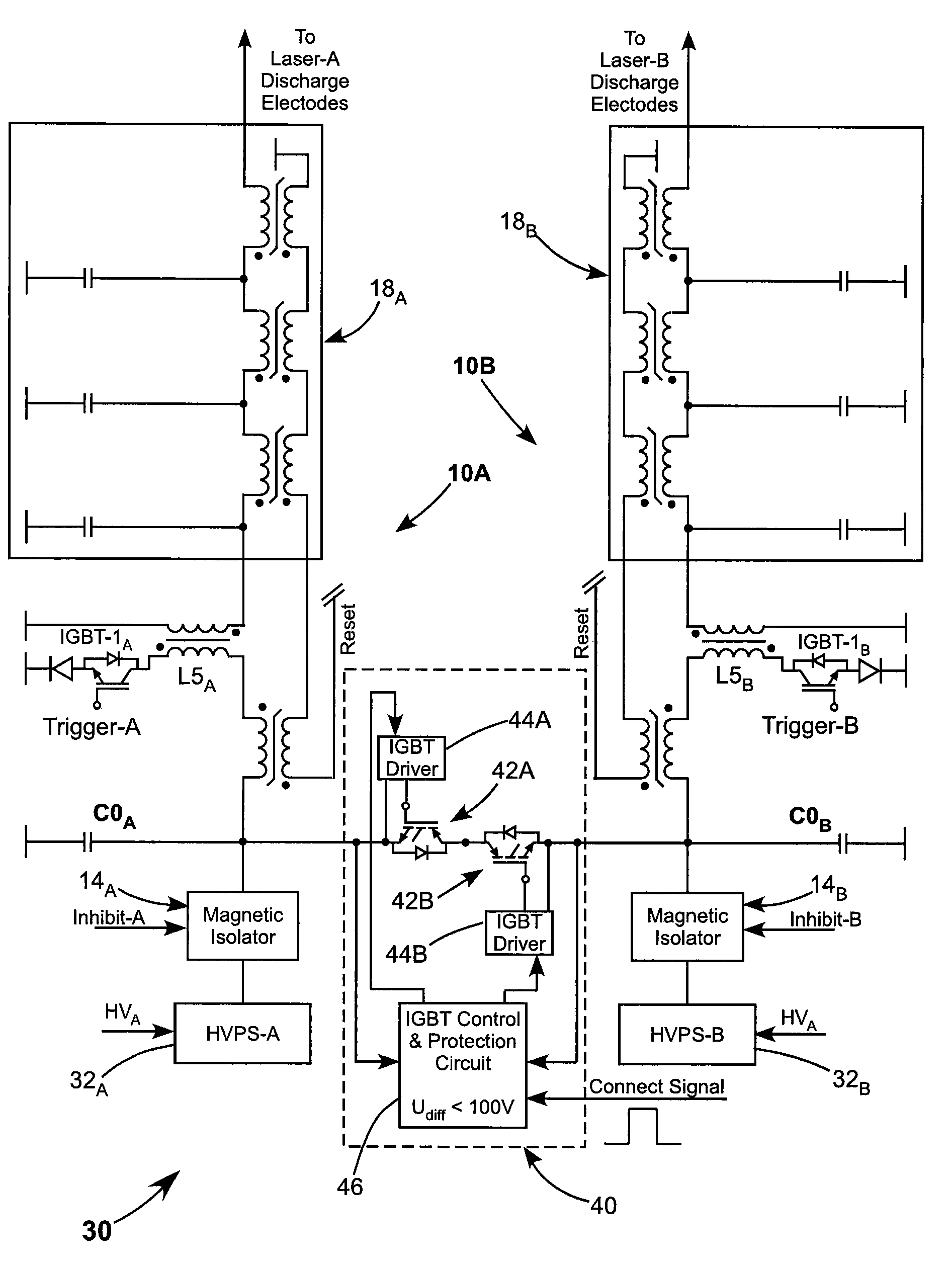
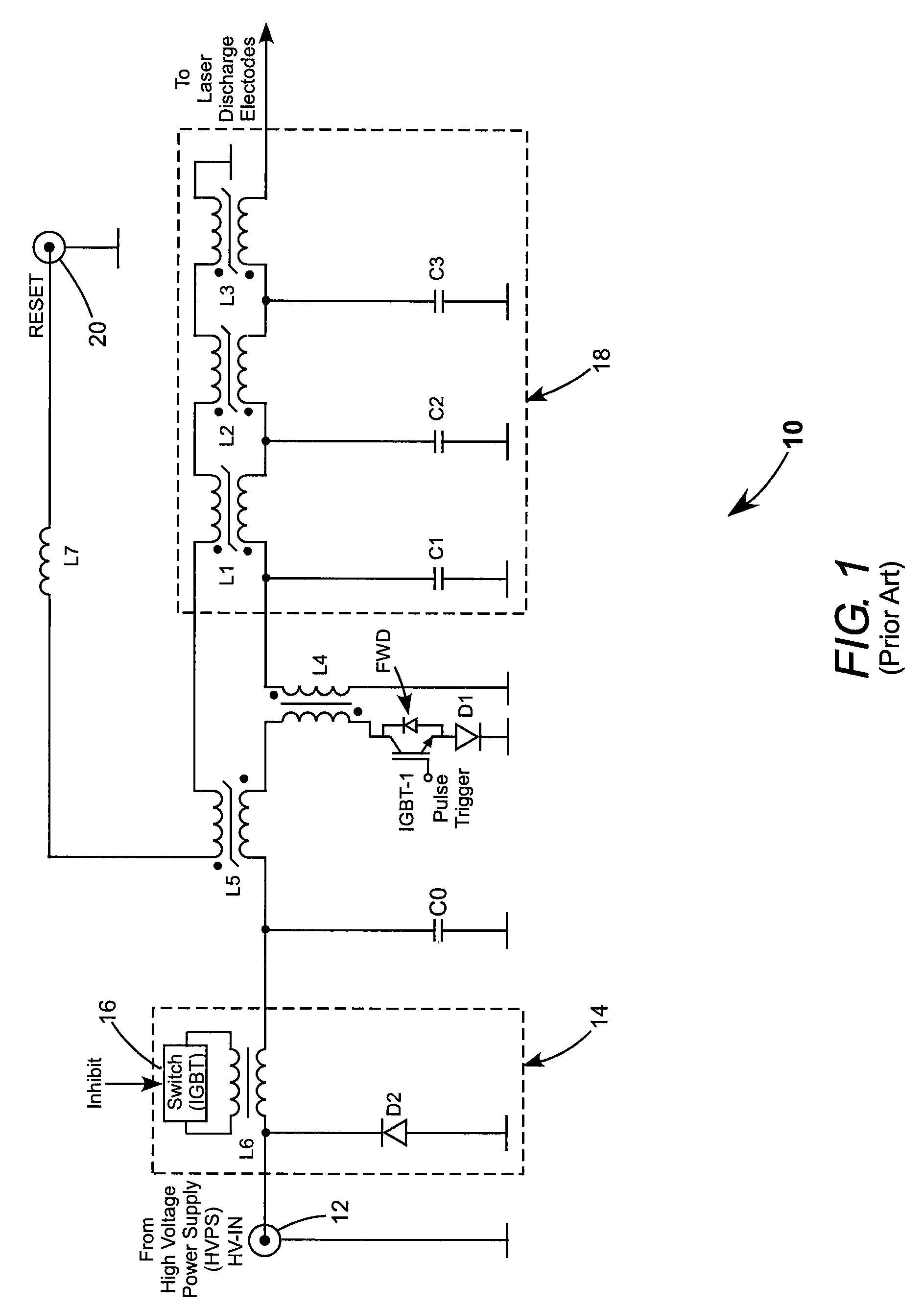
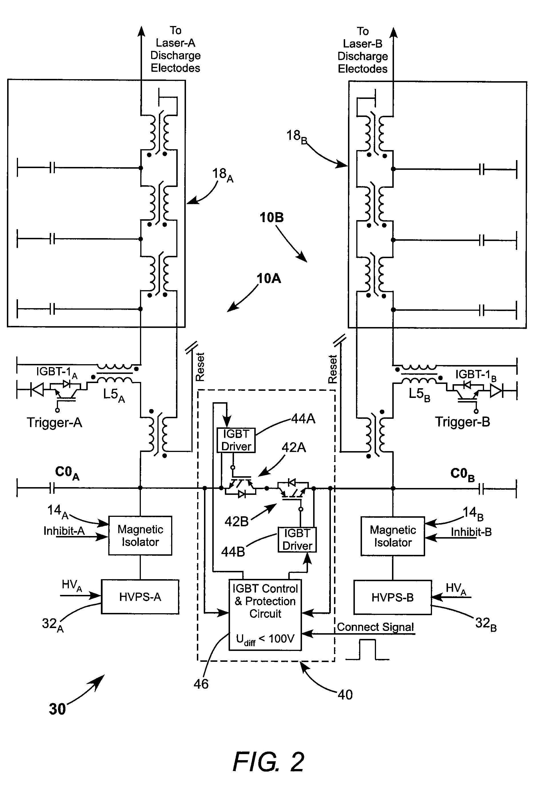
[0020]Continuing now with reference to the drawings, wherein like features are designated by like reference numerals, FIG. 2 is an electrical circuit diagram schematically illustrating a preferred embodiment 10 of apparatus in accordance with the present invention for synchronous operating two excimer lasers (not graphically depicted). The lasers are referred to in FIG. 2 as laser A and laser B. Lasers A and B are energized, individually, by laser pulsing arrangements 10A and 10B respectively, each similar to the above-described prior-art pulsing arrangement 10 of FIG. 1.

[0021]Each pulsing arrangement includes a high-voltage power supply 32 charging a storage capacitor C0 (COA and COB) via a magnetic isolator 14. An electrical pulse is generated by commanding IBGT-1, via a trigger-voltage applied to the gate thereof, to discharge capacitor C0 through a pulse transformer L5 (as discussed above). The magnetic pulse compressor 18 temporally compresses the pulse, and delivers the compre...


PUM


Abstract

Two excimer lasers have individual pulsing circuits each including a storage capacitor which is charged and then discharged through a pulse transformer to generate an electrical pulse, which is delivered to the laser to generate a light pulse. The time between generation of the electrical pulse and creation of the light pulse is dependent on the charged voltage of the capacitor. The capacitors are charged while disconnected from each other. The generation of the electrical pulses is synchronized by connecting the capacitors together for a brief period after the capacitors are charged to equalize the charging voltages. The capacitors are disconnected from each other before they are discharged.

Description

TECHNICAL FIELD OF THE INVENTION[0001]The present invention relates in general to spatial and temporal overlapping of pulses multiple pulsed gas-discharge lasers. The invention relates in particular to spatial and temporal overlapping of pulses from two or more excimer lasers or molecular-fluorine lasers.DISCUSSION OF BACKGROUND ART[0002]Excimer lasers are pulsed gas lasers that deliver radiation in the ultraviolet (UV) region of the electromagnetic spectrum. There are applications of such lasers, for example, laser annealing, that would benefit from a pulse-energy greater than available from the highest energy excimer laser presently available. A greater pulse-energy can be supplied by combining the output of two or more excimer lasers. The output of the lasers must be overlapped spatial and temporally. The spatial overlap can be achieved precisely using an arrangement of optical elements, and optical overlap methods are well known in the art.[0003]The temporal overlap is less prec...

Claims


Application Information

Patent Timeline
Patent Type & Authority Patents(United States)
IPC IPC(8): H01S3/00H01S3/22H01S3/223H01S3/097
CPCH01S3/09702H01S3/225H01S3/2383H01S3/097H01S3/23
Inventor TARGSDORF, ANDREASDESOR, RAINER
Owner COHERENT GMBH
Learn More