
System and method for controlling mode switches in hardware

Active Publication Date: 2012-07-31
NVIDIA CORP
View PDF9 Cites 12 Cited by
  • Summary
  • Abstract
  • Description
  • Claims
  • Application Information

AI Technical Summary

Benefits of technology

[0011]One advantage of the disclosed method is that controlling and executing mode switches primarily in hardware instead of software reduces the quantity of hardware-specific details included in the associated software. Therefore, the software is both simpler and less error-prone relative to software used in prior-art approaches. In addition, by reducing hardware-software interactions, the efficiency of mode switches is increased and, consequently, the length of time that the display devices are blanked or shutdown during some mode switches is decreased.

Problems solved by technology

One drawback to this approach is that implementing such hardware-specific functionality in software has proven to be complicated and error-prone.
In addition, each mode switch may include numerous time-consuming software-hardware related interactions, decreasing overall system efficiency.
Another drawback is that the software may not fully appreciate the limitations of the hardware and, therefore, may schedule a sequence of changes that overburden the hardware.
If the software does not accurately reflect the limitations of the hardware, such as the limited local memory bandwidth, then the sequence of tasks that the software orchestrates to accomplish the mode switch may inadvertently cause the computing system to pass through a transient mode where the display resolution of both of the displays may be set to 1900-by-1200 pixels.
Consequently, the local memory bandwidth may be exceeded, and the data sent to the display devices may become corrupted.

Method used


Image

  • System and method for controlling mode switches in hardware
  • System and method for controlling mode switches in hardware
  • System and method for controlling mode switches in hardware

Examples


Embodiment Construction

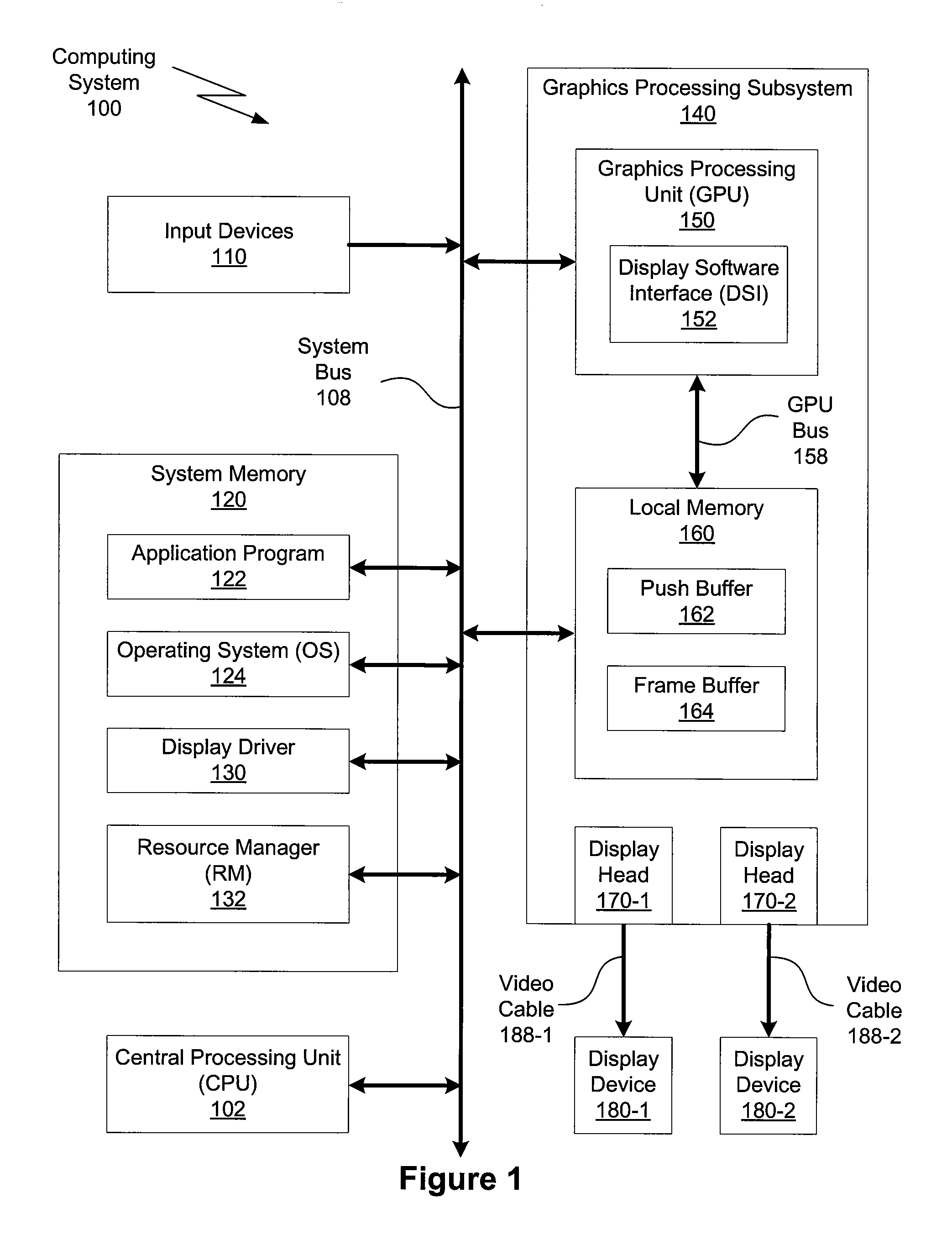
[0018]FIG. 1 is a conceptual diagram of a computing system 100 in which one or more aspects of the invention may be implemented. As shown, the computing system 100 includes a system bus 108, a central processing unit (CPU) 102, input devices 110, a system memory 120, a graphics processing subsystem 140, two display devices 180, and two video cables 188. In alternate embodiments, the computing system 100 may include more or less than two display devices 180 and more or less than two video cables 188. In some embodiments, the CPU 102, portions of the graphics processing subsystem 140, the system bus 108, or any combination thereof, may be integrated into a single processing unit. Further, the functionality of the graphics processing subsystem 140 may be included in a chipset or in some other type of special purpose processing unit or co-processor.

[0019]The system bus 108 connects the CPU 102, the input devices 110, the system memory 120, and the graphics processing subsystem 140. In a...


PUM


Abstract

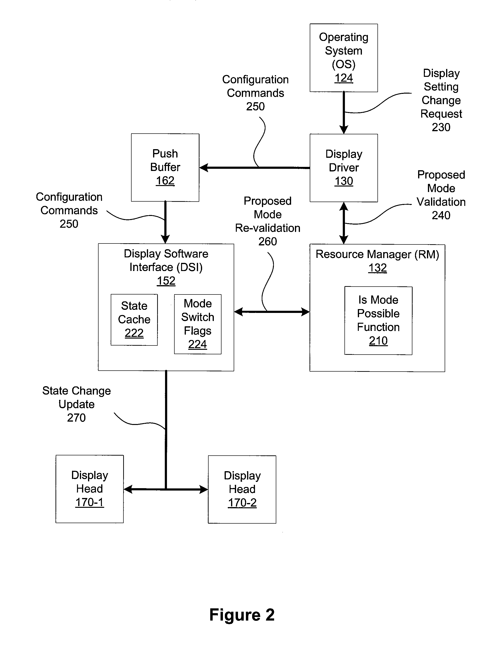
One embodiment of the present invention sets forth a technique for controlling mode switches in hardware. The resource manager includes an “is mode possible” function that evaluates a given mode in conjunction with the limitations of the hardware to determine if the given mode is feasible. The display driver is configured to call this function to validate a proposed mode before generating commands specifying the state changes for the display heads. The display software interface hardware module within the GPU processes these commands and follows a standard sequence of steps to implement the mode switch. The steps may include interrupts to the resource manager to re-validate the proposed mode, again calling the “is mode possible” function, or perform operations that are not yet supported in the hardware. Advantageously, controlling mode switches in hardware enables less error-prone, more efficient, and more discerning mode switches relative to controlling mode switches in software.

Description

CROSS-REFERENCE TO RELATED APPLICATIONS[0001]The current application claims the benefit of U.S. Provisional Application No. 60 / 987,388, filed on Nov. 12, 2007 and having the title, “System and Method for Controlling Mode Switches in Hardware.” This related application is hereby incorporated by reference in its entirety. The current application also claims the benefit of U.S. Provisional Application No. 60 / 988,881, filed on Nov. 19, 2007 and having the title, “System and Method for Controlling Mode Switches in Hardware.” This related application is also hereby incorporated by reference in its entirety.BACKGROUND OF THE INVENTION[0002]1. Field of the Invention[0003]The present invention relates generally to the field of graphics processing and more specifically to a system and method for controlling mode switches in hardware.[0004]2. Description of the Related Art[0005]A typical computing system includes a central processing unit (CPU), an input device, a system memory, one or more gr...

Claims


Application Information

Patent Timeline
IPC IPC(8): G06F1/24G06F9/00
CPCG09G5/363G09G2320/06G09G2360/121G09G2370/04G06F1/3228
Inventor RIACH, DUNCAN A.OGRINC, MICHAEL A.NEFT, LESLIE E.
Owner NVIDIA CORP
Learn More