Liquid crystal display device
a liquid crystal display and display device technology, applied in static indicating devices, semiconductor/solid-state device details, instruments, etc., can solve the problems of increased costs, increased costs, and longer lateral width of fpcs, so as to reduce the length of respective fpcs, reduce the cost of fpcs, and reduce the effect of cumulative dimensional toleran
- Summary
- Abstract
- Description
- Claims
- Application Information
AI Technical Summary
Benefits of technology
Problems solved by technology
Method used
Image
Examples
first embodiment
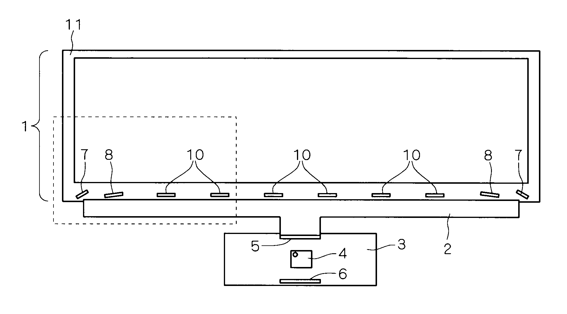
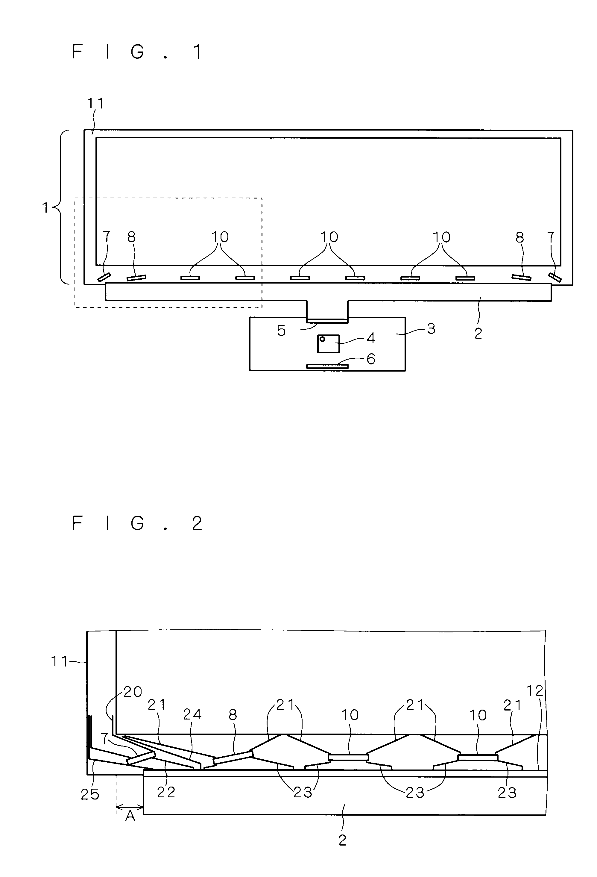
[0026]Prior to describing a liquid crystal display device of the present embodiment, a conventional liquid crystal display device will be described with reference to FIGS. 15 to 18. FIG. 15 is a front view of the conventional liquid crystal display device. As shown in FIG. 15, the conventional liquid crystal display device includes a glass substrate 11, which is an insulating substrate, a liquid crystal panel 1 including a plurality of ICs 9, 10 of COG (Chip On Glass) configuration, an FPC (Flexible Printed Circuit) 2 and a control board 3.
[0027]The plurality of ICs 9, 10 according to FIG. 15 include gate ICs 9 and source ICs 10. As shown in FIG. 15, the plurality of ICs 9, 10 are aligned on the glass substrate 11 at even intervals along a side of the glass substrate 11 which is an insulating substrate. The gate ICs 9 are arranged on both end portions of an alignment of the plurality of ICs 9, 10 while the source ICs 10 are arranged elsewhere. Respective shapes of the plurality of I...
second embodiment
[0052]FIG. 9 is a front view of a liquid crystal display device according to the present embodiment. The FPC 2 according to the present embodiment includes a plurality of FPCs 2a, 2b. As shown in FIG. 9, an FPC 2a is illustrated on the left-hand side of FIG. 9 while an FPC 2b is illustrated on the right-hand side of FIG. 9. Hereinafter, arrangements of the liquid crystal display device according to the present embodiment that are identical to those of the first embodiment will be marked with corresponding reference numerals, and arrangements which are not newly described are deemed to be identical to those of the first embodiment.
[0053]FIG. 10 is a view of a broken line portion of FIG. 9, that is, the FPC 2a illustrated on the left-hand side in FIG. 9 in an enlarged form. In the present embodiment, in each corresponding FPC 2a, 2b, specified ICs are respectively arranged to face towards central sides of the FPC 2a, 2b. In FIG. 10, a gate IC 7a and a source IC 8a, which constitute sp...
third embodiment
[0056]FIG. 12 is a front view of a liquid crystal display device according to the present invention. In the first and second embodiments, the gate ICs 7 are disposed on both end portions of the alignment of the plurality of ICs 7, 8 and 10. According to the present invention, the gate IC 7 is arranged on one end portion of the alignment of the plurality of ICs 7, 8 and 10, for instance, only on the left end portion of the alignment. In this respect, the left end portion of the alignment of the plurality of ICs 7, 8 and 10 is of identical arrangement as that of the first embodiment.
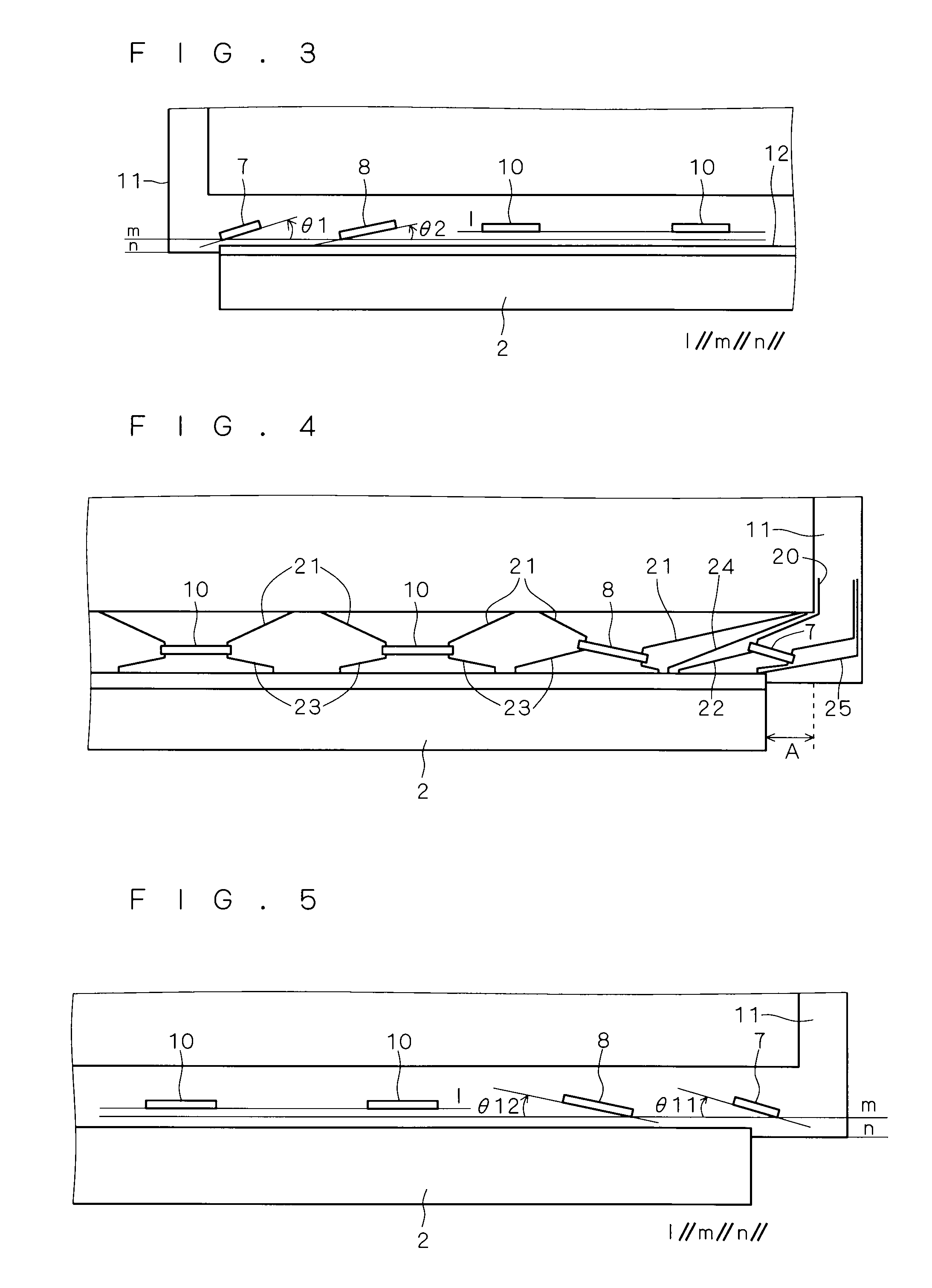
[0057]FIG. 13 is a view of a broken line portion of FIG. 12, that is, a right-hand side of the FPC 2 shown in an enlarged form. According to the present embodiment, specified ICs from among the plurality of ICs 7, 8 and 10 are identical to those of the first embodiment in a point that they are arranged in that extending directions of longer sides thereof are inclined with respect to an extending direction ...
PUM
| Property | Measurement | Unit |
|---|---|---|
| inclination angles | aaaaa | aaaaa |
| thickness | aaaaa | aaaaa |
| length | aaaaa | aaaaa |
Abstract
Description
Claims
Application Information
 - R&D
- Intellectual Property
- Life Sciences
- Materials
- Tech Scout
- Unparalleled Data Quality
- Higher Quality Content
- 60% Fewer Hallucinations
Browse by: Latest US Patents, China's latest patents, Technical Efficacy Thesaurus, Application Domain, Technology Topic, Popular Technical Reports.
© 2025 PatSnap. All rights reserved.Legal|Privacy policy|Modern Slavery Act Transparency Statement|Sitemap|About US| Contact US: help@patsnap.com


