
Mass flow rate control system

a flow rate control and static mixer technology, applied in the direction of liquid transfer devices, process and machine control, instruments, etc., can solve the problems of affecting the chemical reaction in the reactor, generating pressure fluctuations within the mixer, adversely affecting the chemical reaction inside the reactor, etc., to achieve the effect of reducing the stability of the apparatus and the characteristics inside the microreactor

Active Publication Date: 2012-07-31
LONZA AG
View PDF13 Cites 17 Cited by
  • Summary
  • Abstract
  • Description
  • Claims
  • Application Information

AI Technical Summary

Benefits of technology

[0010]With such control of mass flow, in contrast to known CMFCs, the reaction media vessel can be made of any material suitable for the reaction, e.g. steel, glass, email, polymers. Furthermore, the complete controller can be constructed with simple and cheap elements and is not sensitive to environmental influences as conventional CMFCs or other known mass flow controllers.
[0027]Control modes may be switched from automatic to manual or vice versa by the operator. In the latter case, advantageously the manual valve position may be selected as said feedforward valve position. Then a smooth transfer from manual to automatic mode can be achieved, since at first the former pre-selected manual valve position is maintained via the feedforward controller output, and subsequently the difference of actual and target feed flow rate is minimised by the controller output.

Problems solved by technology

Such pumps, however, generate pressure fluctuations within the mixer due to their cycle-periodic characteristics.
Such pressure fluctuations, in particular pressure pulses, as occurring in conventional systems including delivery pumps, may adversely affect the chemical reactions within the reactor (selectivity, reaction mechanism, formation of byproducts etc.), in particular if the reaction is micro-mixing controlled or pressure dependent.
However, these vibrations may degrade the stability of the apparatus and the characteristics inside the microreactor.
Additionally, in order to achieve good precision at low flow rates, a tube with very small diameter (less than 1 mm) is necessary, which may cause additional problems in terms of plugging, clogging etc.
Moreover, a CMFC requires relative long residence time in the metallic structure, so that problems and undesired side effects like chemical reactions, corrosion, apprehensive effort for pre-heating or pre-cooling may arise.

Method used


Image

  • Mass flow rate control system
  • Mass flow rate control system
  • Mass flow rate control system

Examples


Embodiment Construction

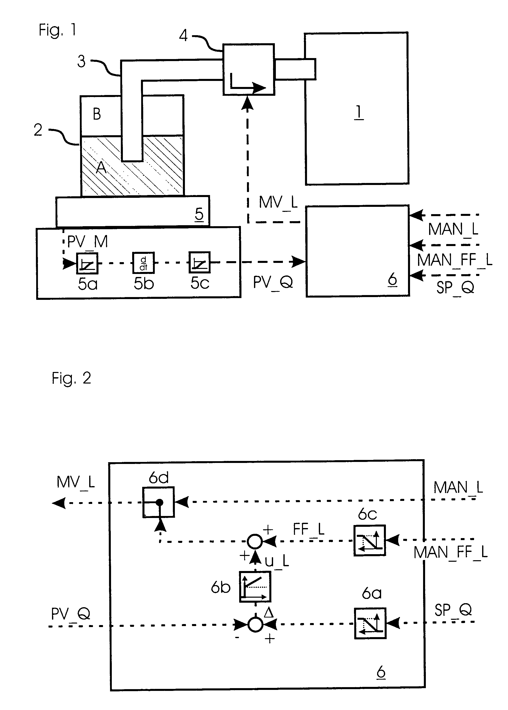
[0032]A dosage system according to an embodiment of the present invention can provide a mixer 1 with a fluid A at a desired flow rate SP_Q without high pressure fluctuations.

[0033]Thereto the system comprises a tank 2 containing said fluid A and an inert fluid B with a predetermined pressure. Said pressure is sufficient to press the fluid A out of tank 2 and into mixer 1.

[0034]Said inert fluid B preferably is an inert gas B, which more preferably is poorly soluble in the fluid. Argon (Ar), Helium (He) or Nitrogen (N2) may be used advantageously as inert gas for example.

[0035]Mixer 1 and tank 2 are connected with one another by a fluid passage 3, wherein a control valve 4 is provided. Said control valve 4 allows adjustment of the actual feed flow rate PV_Q of fluid A delivered to mixer 1. Thereto control valve 4 receives a control signal from a controller 6 in order to adjust the feed flow rate. Said control signal may, for example, indicate a valve position MV_L of control valve 4, ...


PUM


Abstract

A dosage system for feeding a fluid (A) to a static mixer (1), said system comprising a tank (2) containing said fluid (A) at a predetermined pressure, a fluid passage (3) connecting said container (1) and tank (2), a control valve (4) provided within said fluid passage (3) to control the flow of said fluid (A) from said tank into said container; and a controller (6) for receiving a target flow rate (SP_Q) of said fluid (A), and an actual flow rate (PV_Q) of said fluid (A), and for outputting a control signal (MV_L) to said control valve (4) indicating a valve position to adjust the flow rate. Further provided is a method for controlling said dosage system.

Description

[0001]This application is the U.S. National Phase of, and Applicant claims priority from, International Application Number PCT / EP2006 / 010203 filed 23 Oct. 2006 and European Application bearing Serial No. 05023058.0 filed 21 Oct. 2005, which are incorporated herein by reference.BACKGROUND OF THE INVENTION[0002]The present invention relates to a dosage system for a static mixer, in particular a micro-reactor, and a control method thereof.[0003]Static mixers, such as micro reactors, serve for mixing and / or reacting fluids or reactants contained therein. Static mixtures comprise at least one, usually two inlets for the one or more fluids and conventionally said fluids are fed to the mixer by a pump, in particular a piston pump. Such pumps, however, generate pressure fluctuations within the mixer due to their cycle-periodic characteristics. Since in particular in micro-reactors, small-dimensioned static mixers with structured inner cavities and surfaces and with or without temperature co...

Claims


Application Information

Patent Timeline
IPC IPC(8): F16K31/12
CPCG01F1/007G05D7/0635G01F23/20G01F1/86Y10T137/0324Y10T137/7762Y10T137/7759Y10T137/7761
Inventor ROBERGE, DOMINIQUEAMRHEIN, MICHAELGLATZ, YVES
Owner LONZA AG
Learn More