
Automatic group transmission

a transmission group and automatic technology, applied in the direction of mechanical equipment, transportation and packaging, gearing, etc., can solve the problems of synchronized shifting, limiting the life of the transmission as a whole, and affecting the overall shift sequence. , to achieve the effect of synchronizing the shift sequence, limiting the life of the transmission as a whole, and reducing the transmission speed

Inactive Publication Date: 2012-07-31
ZF FRIEDRICHSHAFEN AG
View PDF11 Cites 9 Cited by
  • Summary
  • Abstract
  • Description
  • Claims
  • Application Information

AI Technical Summary

Benefits of technology

This design enables faster range shifts and reduces the time delay associated with shifting operations, as changes occur during synchronization of the main transmission, without affecting shifts not involving the range-change group.

Problems solved by technology

However, since many of the shift operations in a group transmission entail changing transmission ratio steps in more than one of the partial-transmissions, and therefore take place in a relatively complex manner, most of the known group transmissions are designed to be shifted by either partial or full automation.
However, since synchronized shifting clutches are expensive, because of their complex structure, take up a relatively large amount of structural space, and limit the life of the transmission as a whole because of wear, it is intended in future designs of such group transmissions to design the range-change group, in addition to the main transmission, with claw-shifting means.
Since an automated gate change, in each case, entails controlling and stopping the associated adjusting drive, sensing that the first shifting packet is in the neutral position, switching between the two gates or shifting packets and controlling and sensing the adjusting drive in the target shift position(s) of the second shifting packet, a gate change has a disadvantageous delaying effect on the shift sequence as a whole.

Method used


Image

  • Automatic group transmission
  • Automatic group transmission
  • Automatic group transmission

Examples


Embodiment Construction

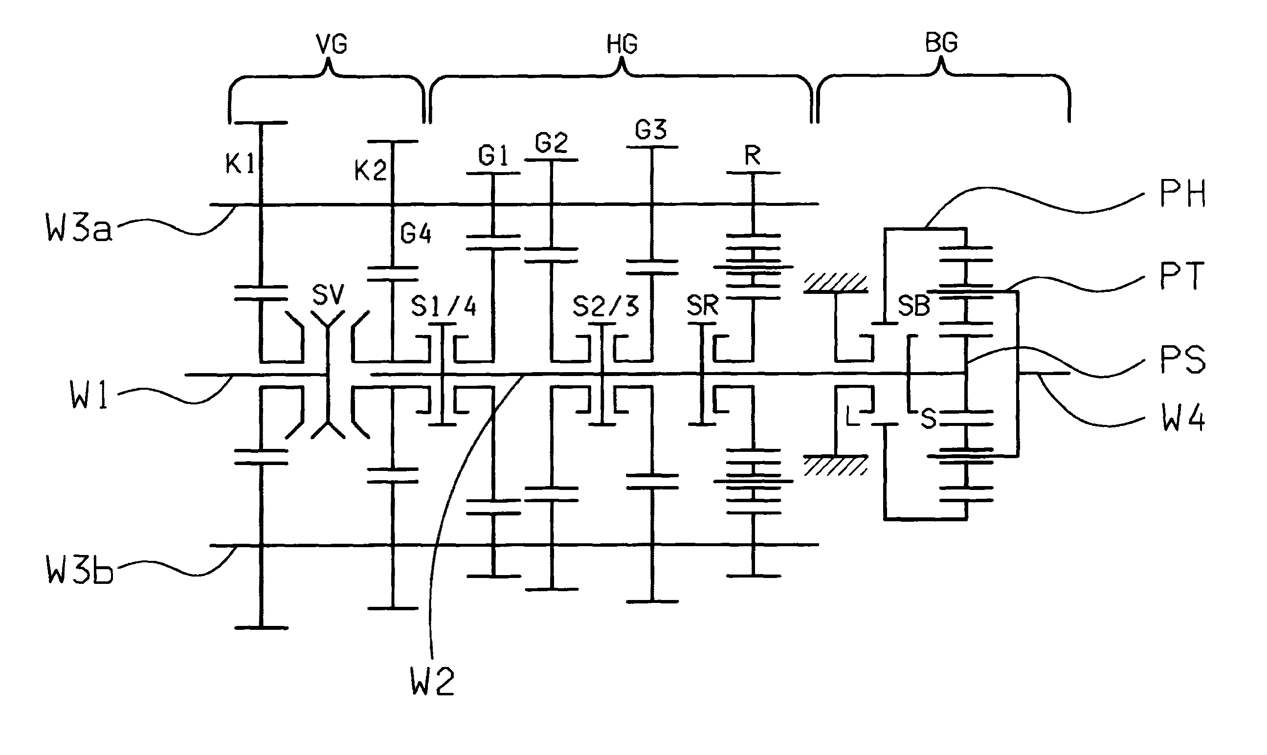
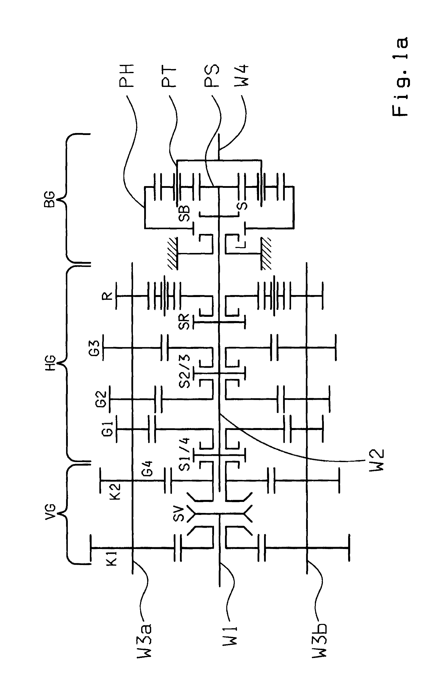
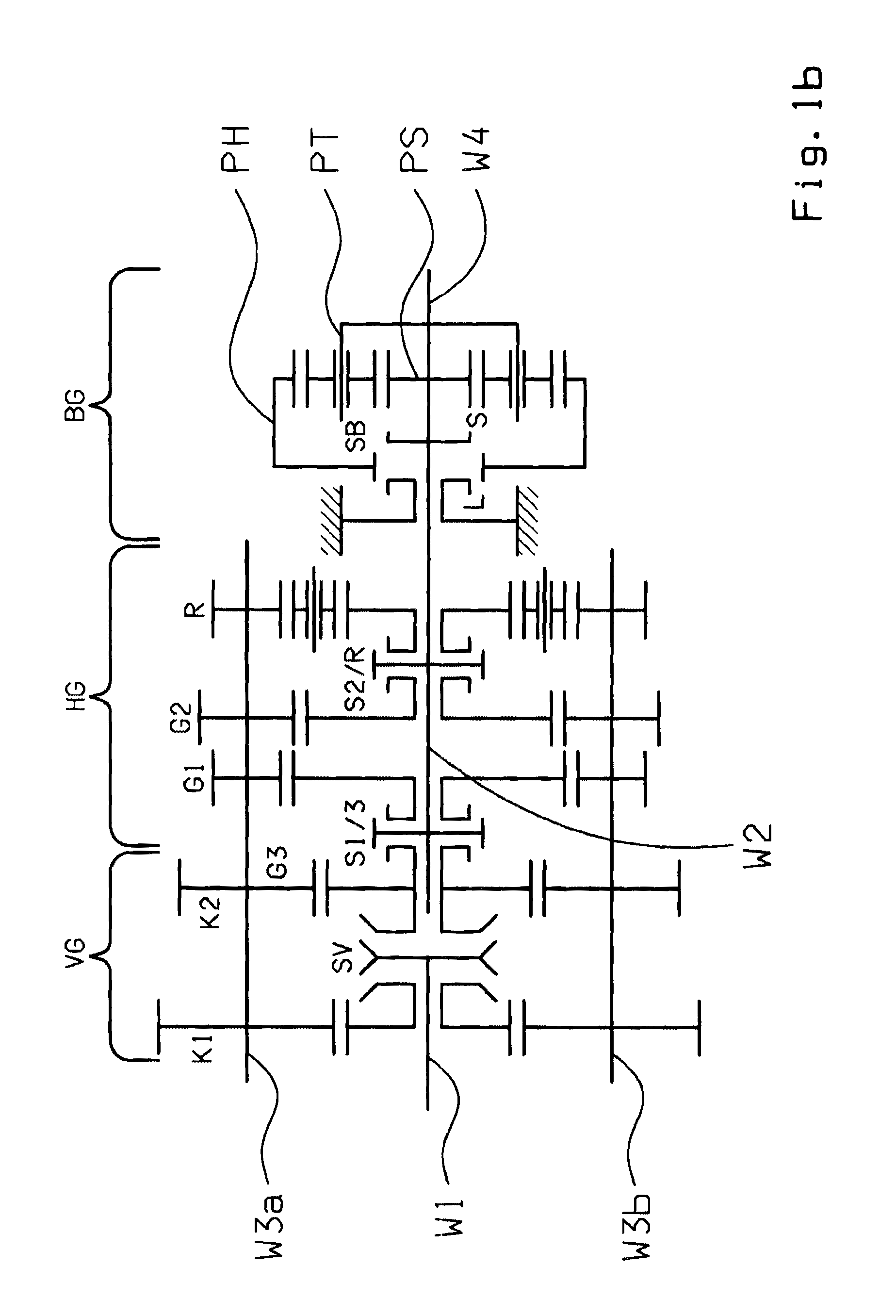
[0029]FIGS. 1a and 1b show schematic representations of example structures of the group transmissions according to the invention. The main transmission HG is of countershaft design and has a main shaft W2 and two countershafts W3a, W3b. In the embodiment according to FIG. 1a, the main transmission HG is a four-stage transmission with four transmission ratio steps G1 to G4 for forward driving and one transmission ratio R for reversing. In the version according to FIG. 1b, the main transmission HG is a three-stage transmission with three transmission ratio steps G1 and G3 for forward driving and one transmission ratio R for reversing.

[0030]The loose wheels of the transmission ratio steps G1, G2, G3 and R or G1, G2 and R, respectively, are in each case mounted to rotate on the main shaft W2 and can be engaged by means of claw clutches. The associated fixed wheels are arranged rotationally fixed on the two countershafts W3a and W3b. The respective highest transmission ratio step G4 or G...


PUM


Abstract

An automated group transmission having a multi-stage main transmission (HG), a splitter group (VG) connected upstream from the main transmission (HG) and a two-stage range-change group (BG) connected downstream of the main transmission (HG), such that the splitter group (VG) is connected, via a controllable separator clutch, to a drive motor. The main transmission (HG) and the range-change group (BG) are of either a synchronized or an unsynchronized design and the shifting clutches of two respective transmission ratio steps, in at least one of the partial-transmissions (VG, HG, BG), are respectively combined in a common shifting packet with two shift positions and a neutral position. To speed up most range shifts, it is provided that in the main transmission (HG) the shifting clutches associated with the lowest transmission ratio step (G1) and with the highest transmission ratio step (G4 or G3) are combined in a common shifting packet (S1 / 4 or S1 / 3).

Description

[0001]This application is a National Stage completion of PCT / EP2008 / 052163 filed Feb. 22, 2008, which claims priority from German patent application serial no. 10 2007 010 828.3 filed Mar. 6, 2007.FIELD OF THE INVENTION[0002]The invention concerns an automated group transmission.BACKGROUND OF THE INVENTION[0003]Group transmissions with a multi-gear main transmission, an upstream group in drive connection upstream from the latter and a range-change group in drive connection downstream thereof, have been known for a long time and are preferably used in utility vehicles. By designing the upstream group, which usually has two stages and can also be called the splitter group, with a small transmission ratio interval, the transmission ratio intervals between the transmission ratio steps of the main transmission are approximately halved and the total number of transmission ratio steps available is thus doubled. By virtue of a usually two-stage range-change group, the spread of the transmis...

Claims


Application Information

Patent Timeline
Patent Type & Authority Patents(United States)
IPC IPC(8): F16H3/08
CPCF16H37/046F16H3/095F16H3/097F16H61/702Y10T74/19242F16H2306/48Y10T74/19019Y10T74/19233F16H2200/003
Inventor MILLER, MARTINDOEBELE, BERNDBADER, JOSEF
Owner ZF FRIEDRICHSHAFEN AG
Learn More