
System and method for conditional biventricular pacing

a conditional biventricular and pacing technology, applied in the field of implantable medical devices, can solve the problems of increased poor pump function, heart failure and death, etc., and achieve the effect of improving efficiency and reducing the risk of atrial fibrillation

Active Publication Date: 2012-07-24
MEDTRONIC INC
View PDF125 Cites 1 Cited by
  • Summary
  • Abstract
  • Description
  • Claims
  • Application Information

AI Technical Summary

Benefits of technology

This approach reduces the risks of heart failure and death by promoting intrinsic conduction and synchrony, correcting prolonged AV intervals, and minimizing LV desynchronization, thereby improving cardiac function and reducing adverse pacing-related complications.

Problems solved by technology

As an example, many systolic heart failure patients with intact AV conduction and proper intrinsic rate control also have ventricular conduction disturbances which cause regional mechanical delay (contraction asynchrony) that worsens pump function.
Currently, application of biventricular pacing is confined to patients with systolic heart failure and ventricular conduction delay that occurs spontaneously or is imposed by obligatory RV pacing.
Over time, there has been recognition in the field that RV apical (RVA) pacing (i.e., only providing ventricular pacing in the right ventricular apex), despite maintenance of AV synchrony, is associated with increased risks of atrial fibrillation, heart failure and death.
These adverse effects are attributed to disruptions to AV timing and an asynchronous ventricular contraction sequence obligated by RVA-only pacing.
While these kinds of pacing protocols provide ever safer and efficacious therapies for various patient populations, there remain numerous other patient populations that lack an effective pacing therapy to address their cardiac condition.

Method used


Image

  • System and method for conditional biventricular pacing
  • System and method for conditional biventricular pacing
  • System and method for conditional biventricular pacing

Examples


Embodiment Construction

[0020]FIG. 1 depicts an implantable medical device (IMD) embodied as a multi-chamber cardiac pacemaker or implantable pulse generator (IPG) 14. While an IPG is illustrated, it will be appreciated that embodiments may be provided that include and implantable cardioverter defibrillator (ICD) having pacing capabilities. The multi-chamber IPG 14 is configured to deliver pacing pulses to one or more heart chambers as needed to control the heart activation sequence or provide other therapy. The IPG 14 is shown in communication with patient's heart 10 by way of three leads 16, 32 and 52. The heart 10 is shown in a partially cut-away view illustrating the upper heart chambers, the right atrium (RA) and left atrium (LA), and the lower heart chambers, the right ventricle (RV) and left ventricle (LV), and the coronary sinus (CS) extending from the opening in the right atrium laterally around the atria to form the great cardiac vein 48, which branches to form inferior cardiac veins.

[0021]The IP...


PUM


Abstract

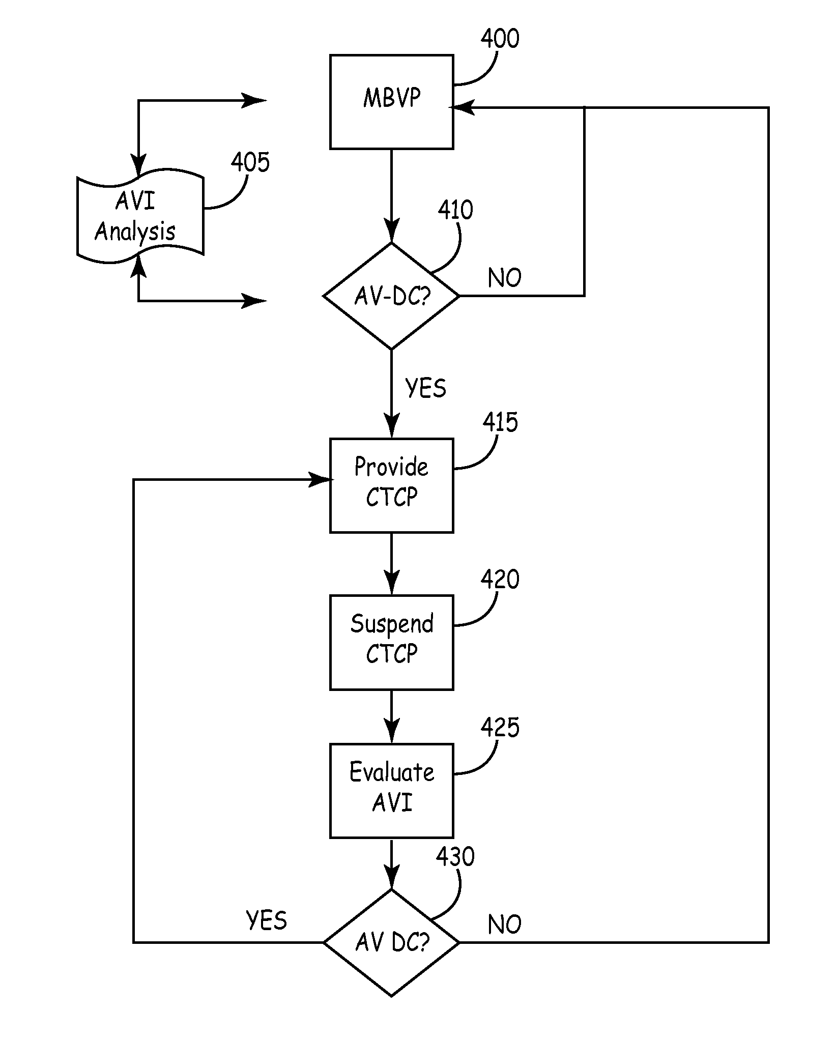
An implantable pacing system with single, double and triple chamber pacing capabilities, provided individually or in concert on a conditional or continuous basis depending upon ongoing analyses of atrial rhythm status, atrioventricular conduction status and ventricular rate. A mode is selected to reduce the occurrence of any ventricular pacing in favor of intrinsic atrioventricular and ventricular conduction. If excessively long PR intervals are occurring too frequently or atrioventricular conduction is unreliable or absent, the implantable pulse generator is operated in a conditional triple chamber pacing mode that provides atrial-synchronous biventricular pacing in every cardiac cycle for a period of time as necessary to restore and maintain AV synchrony, while minimizing ventricular asynchrony otherwise associated with monochamber RV pacing as in conventional dual chamber pacing systems. Similarly, biventricular pacing is provided in every cardiac cycle when ventricular rates are undesirably slow during atrial fibrillation, where AV synchronization is excluded.

Description

RELATED APPLICATION[0001]The present application claims priority and other benefits from U.S. Provisional Patent Application Ser. No. 61 / 156,197, filed Feb. 27, 2009, entitled “A SYSTEM AND METHOD FOR CONDITIONAL BIVENTRICULAR PACING, incorporated herein by reference in it's entirety.FIELD OF THE INVENTION[0002]The present disclosure relates to implantable medical devices and more particularly, implantable medical devices that provide biventricular pacing.BACKGROUNDDescription of the Related Art[0003]Implantable medical devices (“IMDs”) provide various cardiac therapies including pacing, cardioversion and defibrillation. Initially, the primary purpose of a pacing therapy was to prevent symptomatic bradycardia due to disorders of impulse formation (i.e., sinus node dysfunction) or propagation (i.e., atrioventricular block).[0004]Pacing systems evolved with the goal of providing full control of the electrical timing of the heart in order to more closely mimic the precise electromechan...

Claims


Application Information

Patent Timeline
Patent Type & Authority Patents(United States)
IPC IPC(8): A61N1/368
CPCA61N1/3622A61N1/3682
Inventor SWEENEY, MICHAEL O.SHELDON, TODD J.
Owner MEDTRONIC INC
Learn More