
Apparatus and method for measuring carrier to interference and noise ratio

a carrier interference and noise ratio technology, applied in the field of apparatus and methods for measuring carrier interference and noise ratio, can solve the problems of large error between measured cinr values in real communication systems, waste of power, and complicated processes, and achieve the effect of minimizing separately added processes and efficiently configuring hardware/softwar

Active Publication Date: 2012-07-24
WIRELESS ALLIANCE LLC
View PDF19 Cites 2 Cited by
  • Summary
  • Abstract
  • Description
  • Claims
  • Application Information

AI Technical Summary

Benefits of technology

This approach enables more precise and efficient measurement of CINR, maximizing throughput and maintaining constant signal intensity, while adapting transmission power to variable communication conditions, thus enhancing overall communication quality and minimizing unnecessary processes.

Problems solved by technology

Further, because it is supposed that all terminals and users have the same noise and the same interference in this US patent, an error between measured CINR values may become larger in real communication systems which are different according to terminals or users.
Like the above US patent, this Korean Patent supposes that all terminals or users have the same noise and the same interferences while estimating noise and interference components, but this is not the case in real wireless conditions.
Further, in the Korean Patent, when the received signal is demodulated, a new block is needed separately from channel compensation or channel estimation according to varied channel conditions, so that processes may be complicated and power is wastefully consumed.

Method used


Image

  • Apparatus and method for measuring carrier to interference and noise ratio
  • Apparatus and method for measuring carrier to interference and noise ratio
  • Apparatus and method for measuring carrier to interference and noise ratio

Examples


Embodiment Construction

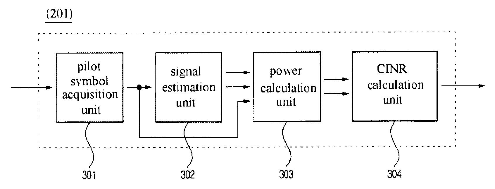
[0045]In the drawing figures:[0046]301: Pilot symbol acquisition unit[0047]302: Signal estimation unit[0048]303: Power calculation unit[0049]304: CINR calculation unit[0050]501: Interpolation operation unit[0051]502: Average operation unit[0052]503: Gain mapping unit

[0053]For reference, a “communication terminal” includes a personal digital cellular (PDC) phone, a personal communication service (PCS) phone, a personal handy phone system (PHS) phone, a code division multiplexing access (CDMA)-2000(1X, 3X) phone, a wideband code division multiplexing access (WCDMA) phone, a dual band / dual mode phone, a global standard for mobile (GSM) phone, a mobile broadband system (MBS) phone, a digital multimedia broadcasting (DMB) phone, a terminal, a smart phone, an orthogonal frequency division multiplexing (OFDM) communication terminal, an orthogonal frequency division multiplexing access (OFDMA) communication terminal, a personal digital assistant (PDA), a hand-held personal computer, a noteb...


PUM


Abstract

Provided are an apparatus and method for measuring a carrier-to-interference and noise ratio (CINR) using a pilot symbol in a digital communication system, and more particularly, to an apparatus and method for measuring a CINR by estimating a data signal, noise, and an interference signal from a pilot symbol in a digital communication system using orthogonal frequency division multiplexing (OFDM) / orthogonal frequency division multiplexing access (OFDMA). The apparatus includes: a pilot symbol acquisition unit for acquiring the pilot symbol from a baseband frequency signal; a signal estimation unit for estimating a pilot signal and a data signal from the pilot symbol; a power calculation unit for calculating a power value of the estimated data signal and calculating a power value of a noise signal from a difference between the pilot symbol and an estimated pilot signal; and a CINR calculation unit for calculating a CINR on the basis of the power values of the data and noise signals. Thus, a pilot symbol is used for more easily and precisely measuring a CINR of a received signal, and scheduling of a base station and transmission power control of a terminal are performed on the basis of the measured CINR.

Description

CROSS-REFERENCE TO RELATED APPLICATIONS[0001]The present application is a National Phase of PCT / KR2006 / 005802, filed Dec. 28, 2006, which claims the benefit of Korean Application No. 10-2005-0134648, filed Dec. 30, 2005, the entire disclosures of which are incorporated herein by reference.FIELD OF THE INVENTION[0002]1. Technical Field[0003]The present invention relates to an apparatus and method for measuring a carrier- to-interference and noise ratio (CINR) using a pilot symbol in a digital communication system, and more particularly, to an apparatus and method for measuring a CINR by estimating a data signal, noise, and an interference signal from a pilot symbol in a digital communication system using orthogonal frequency division multiplexing (OFDM) / orthogonal frequency division multiplexing access (OFDMA).[0004]2. Background of the Invention[0005]In the case that a signal is transmitted through multi-path channels, a received signal is affected by an inter-symbol interference (I...

Claims


Application Information

Patent Timeline
Patent Type & Authority Patents(United States)
IPC IPC(8): H03D1/04
CPCH04L5/0048H04B17/336H04W52/241H04W52/246H04B17/26H04L27/2647H04L5/0007H04L5/0037H04L25/0232H04B17/24H04L27/26
Inventor KWAK, KI YOUNGLEE, KANG MINOH, JI MYUNGHWANG, YONG SUK
Owner WIRELESS ALLIANCE LLC
Learn More