
Thin linear seatbelt pretensioner

a seatbelt and pretensioner technology, applied in the direction of safety belts, pedestrian/occupant safety arrangements, vehicular safety arrangements, etc., can solve the problems of affecting the repeatability of the performance of the plp, the uneven shape of the affixed piston, and the significant volume of gas produced by the gas generator. , to achieve the effect of reducing the stroke distance needed, reducing the bulk of the assembly, and reducing the leak path

Active Publication Date: 2012-07-24
AUTOLIV ASP INC
View PDF35 Cites 4 Cited by
  • Summary
  • Abstract
  • Description
  • Claims
  • Application Information

AI Technical Summary

Benefits of technology

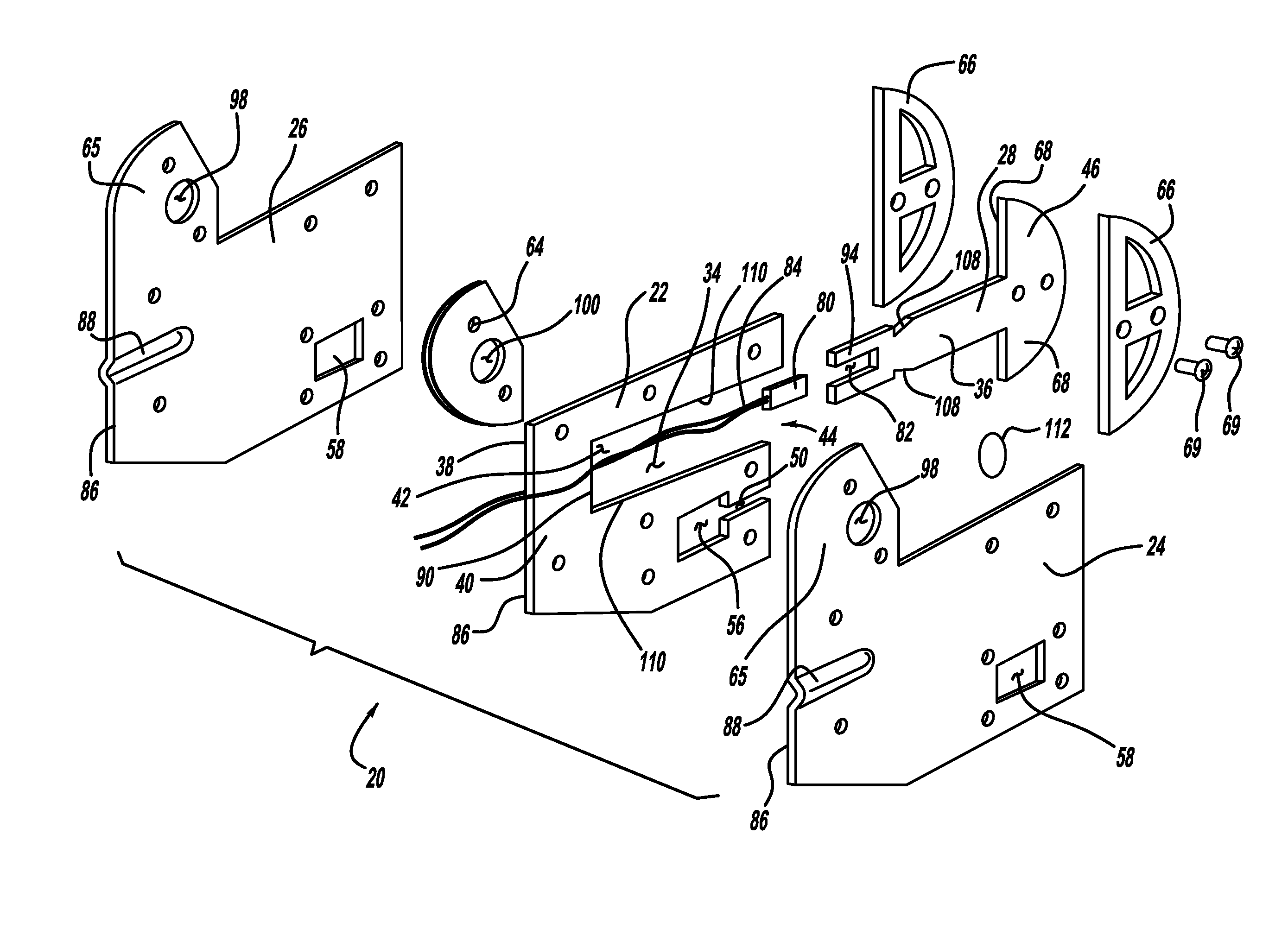
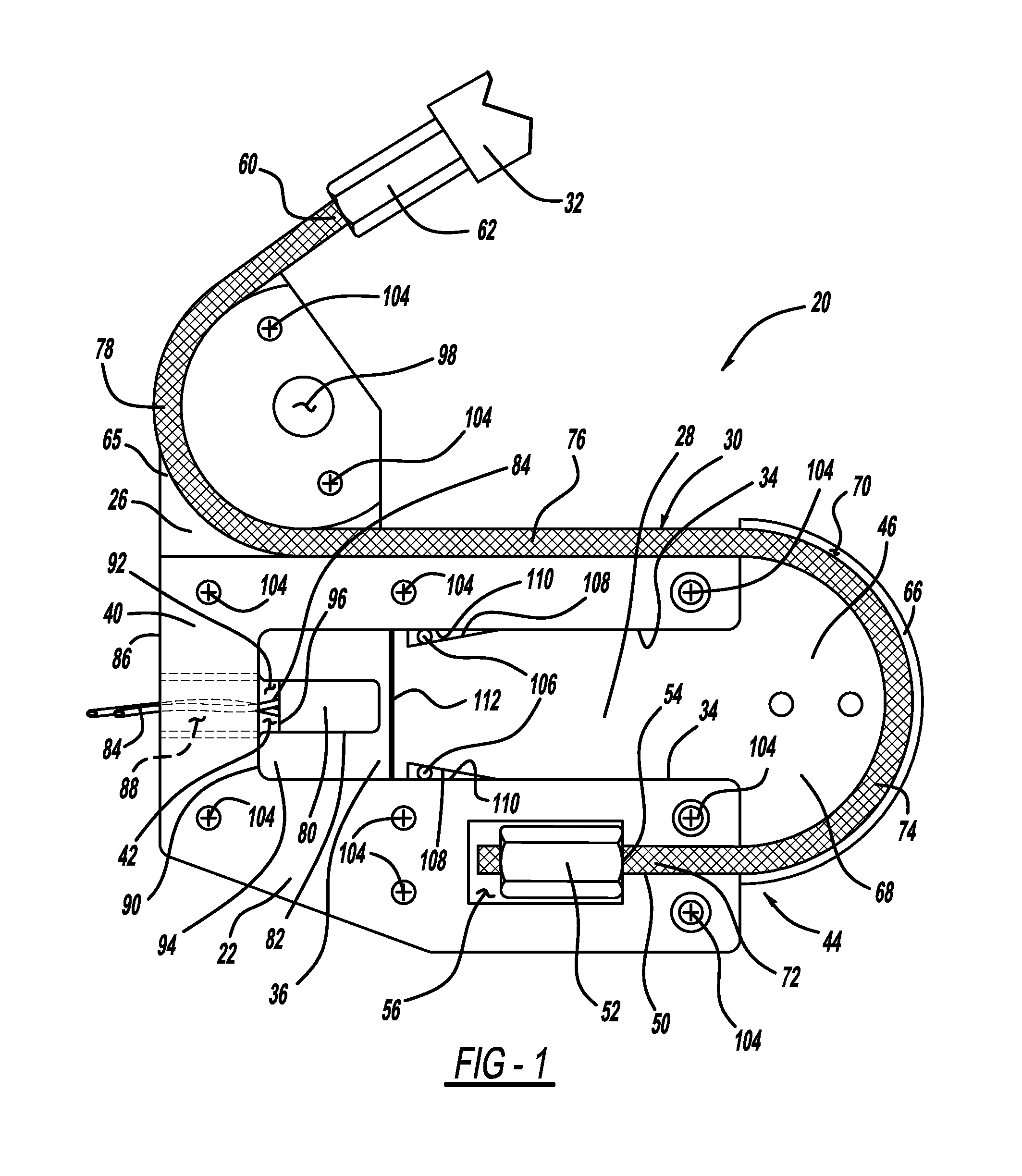
The present invention provides a pretensioner that reduces leak paths for gas to escape from the device, eliminates the need for expensive die cast components, reduces the stroke distance needed for the piston, and reduces the bulk of the assembly. The pretensioner includes a base plate and a closure plate that form a cavity with a piston tail and a piston head that can be activated by a gas generator to exert tension on a cable. The invention can take different forms and has various benefits for the art to which it relates.

Problems solved by technology

One design challenge with current linear and buckle pretensioners utilizing gas generators is efficient utilization of the gas volume produced by the generator.
Typically, a significant volume of the gas produced by the gas generator leaks out of the device.
A cable affixed to the piston typically has an uneven shape that is very difficult to seal around.
Moreover, manufacturing variations and the related lack of control of leakage paths can affect the repeatability of performance of the PLP.
Typical PLPs utilize a round cylinder piston arrangement which makes the assembly bulky which limits ease of implementation, such as when it is desired to mount the unit behind interior trim panels or adjacent to vehicle seats.
In addition, the components of many presently available PLP devices are die cast, which compared with many other manufacturing processes, is expensive.

Method used


Image

  • Thin linear seatbelt pretensioner
  • Thin linear seatbelt pretensioner
  • Thin linear seatbelt pretensioner

Examples


Embodiment Construction

[0024]The following description is merely exemplary in nature and is not intended to limit the present disclosure or its application or uses.

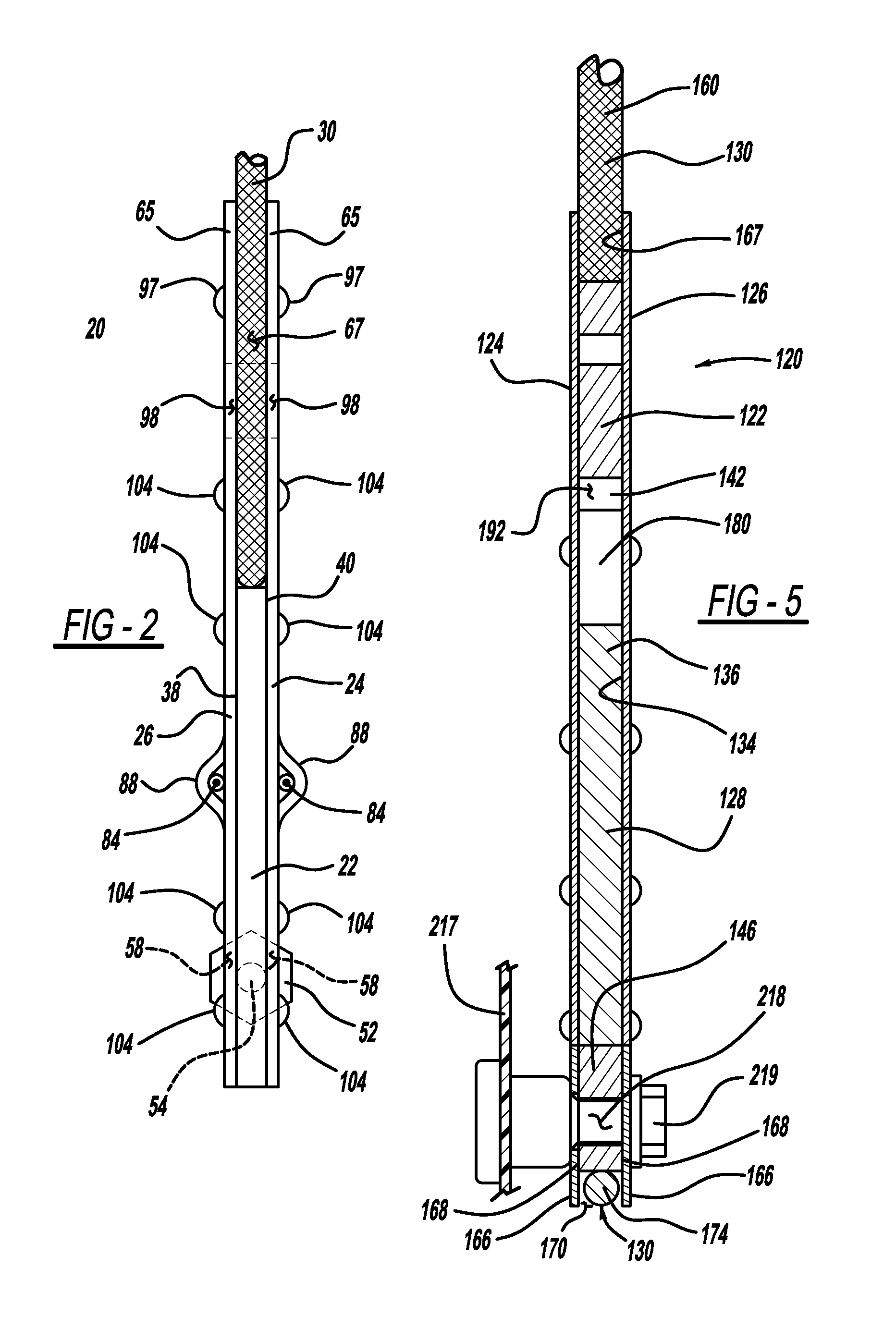
[0025]Referring now to FIGS. 1-3, a linear pretensioner in accordance with the present invention is illustrated and generally designated by reference number 20. The pretensioner 20 includes a base plate 22, front and back closure plates 24 and 26, a piston plate 28 and a cable 30. In this example, the linear pretensioner 20 is used as part of a motor vehicle occupant belt restraint system of the type mountable to a motor vehicle structure and coupled with a belt restraint system component 32. Each of the base plate 22, the closure plates 24 and 26, and the piston plate 28 is substantially flat, but they may have cut-outs and / or indented portions as described herein.

[0026]The base plate 22 has portions forming a slot 34 for receiving the piston tail 36 of the piston plate 28. The piston tail 36 is slidably disposed within the slot 34. The base p...


PUM


Abstract

A linear pretensioner for use as part of a motor vehicle occupant belt restraint system mountable to vehicle structure and coupled with a belt restraint system component. The pretensioner includes at least one base plate having a slot and at least one closure plate fixedly attached to the base plate. The closure plate(s) and the slot of the base plate(s) form a cavity having an open end. A piston plate has a piston tail slidably disposed within the cavity and a piston head extending from the open end. A cable is coupled with the piston plate, the base plate(s), and / or the closure plate(s). The piston plate, the slot of the base plate(s), and the closure plate(s) cooperate to form an expanding chamber that enlarges when pressurized by a gas generator, which drives the piston plate and the base plate relative to each other to exert tension on the cable.

Description

FIELD OF THE INVENTION[0001]The present invention relates generally to seatbelt restraint systems for motor vehicles, and more particularly, to a linear seatbelt pretensioner for a seatbelt restraint system.BACKGROUND OF THE INVENTION[0002]Seatbelt restraint systems for restraining an occupant in a vehicle seat play an important role in reducing occupant injury in vehicle crash situations. Seatbelt restraint systems of the conventional so-called “3-point” variety commonly have a lap belt section extending across the seat occupant's pelvis and a shoulder belt section crossing the upper torso, which are fastened together or are formed by a continuous length of seatbelt webbing. The lap and shoulder belt sections are connected to the vehicle structure by anchorages. A belt retractor is typically provided to store belt webbing and may further act to manage belt tension loads in a crash situation.[0003]Seatbelt restraint systems which are manually deployed by the occupant (so-called “act...

Claims


Application Information

Patent Timeline
Patent Type & Authority Patents(United States)
IPC IPC(8): B60R22/46
CPCB60R22/1952B60R22/1955
Inventor LANE, JR., WENDELL CHENNEY
Owner AUTOLIV ASP INC
Learn More