
Pre-charging an inverter using an auxiliary winding

a technology of inverter and auxiliary winding, which is applied in the direction of dc circuit to reduce harmonics/ripples, automatic control of ignition, instruments, etc., can solve the problems of converter fuses, voltage ripple in dc bus, and significantly reduce the reliability and life expectancy of modules

Active Publication Date: 2012-07-17
TECO WESTINGHOUSE MOTOR
View PDF51 Cites 49 Cited by
  • Summary
  • Abstract
  • Description
  • Claims
  • Application Information

AI Technical Summary

Benefits of technology

"The present invention is about a transformer module for a medium voltage drive system. The module has a main primary winding that receives a medium voltage signal, multiple main secondary windings that power the drive's cells, and an auxiliary primary winding that receives a low voltage signal. The auxiliary primary winding can be activated during pre-charging or power loss events to provide the low voltage signal to the cells. The system also includes a transformer module switch that can switch between the low voltage and medium voltage signals. The method of controlling the drive system involves switching the low voltage signal to the auxiliary primary winding for pre-charging, and then switching to the medium voltage signal when a certain voltage level is reached. This invention allows for efficient and reliable operation of the drive system."

Problems solved by technology

Hence, the output energy of a capacitor bank of the power cell also varies and causes voltage ripple in the DC bus.
This high in-rush current can severely stress the converter's fuses, input rectifiers, transformers and power switches, and can significantly reduce the reliability and life expectancy of the modules.
Industrial facilities such as manufacturing plants often have multiple supplies on a line, and the combined in-rush current can trip a circuit breaker.
The resulting unplanned downtime is extremely expensive and reduces the profits.
Large in-rush currents degrade the performance and lifetime of a drive in a number of ways.
The sparking of the switch contacts leads to premature switch failure; it can also cause the line circuit breaker to trip, especially if there are multiple power supplies on the same circuit; the current can thermally over-stress the input rectifiers, causing immediate power cell failure; high currents on the fuse cause heating, which can slowly degrade the fuse over time; and high in-rush current also stresses the transformer modules and reduces their life or may cause failure in windings.
Thus large in-rush current to a drive at power-up challenges designers to apply different techniques to control the capacitor in-rush current by using pre-charge circuits.
However, known pre-charge circuits can be complex and significantly add to component costs, increase size and weight of the drive, and can have reliability issues.

Method used


Image

  • Pre-charging an inverter using an auxiliary winding
  • Pre-charging an inverter using an auxiliary winding
  • Pre-charging an inverter using an auxiliary winding

Examples


Embodiment Construction

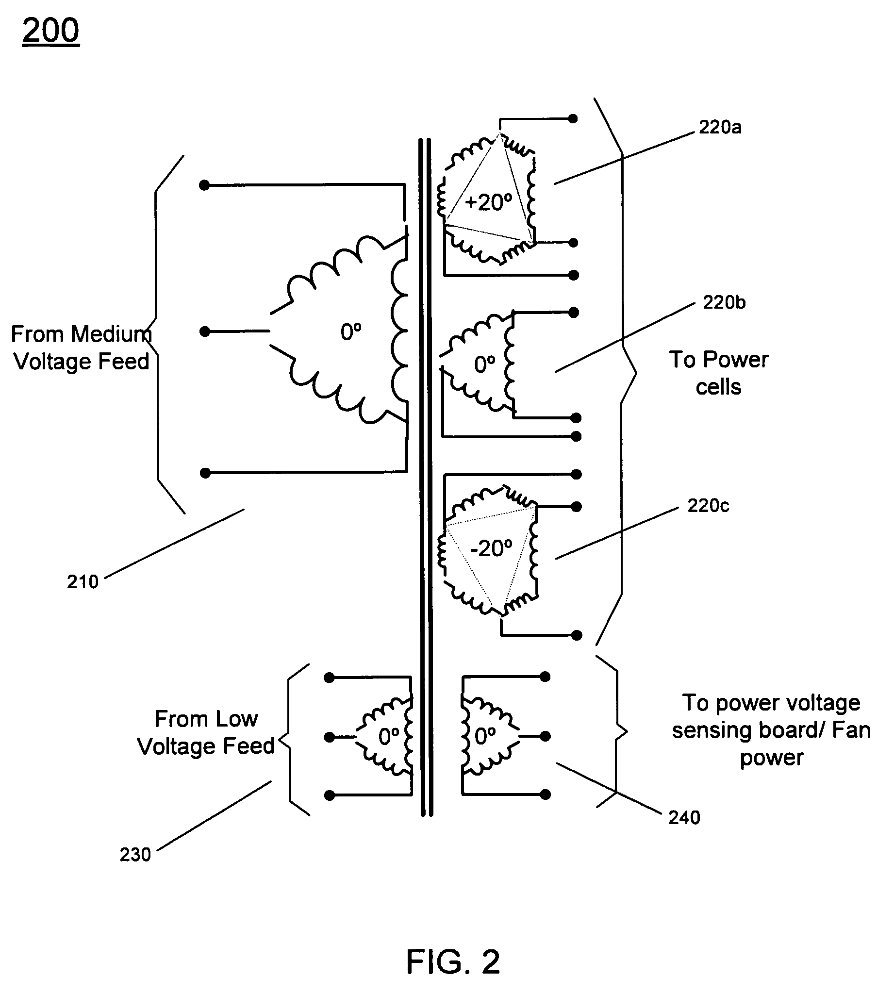
[0019]In various embodiments pre-charging of cascaded medium voltage drives (both symmetric and asymmetric) can be realized using an auxiliary power source, such as provided through an auxiliary coil of a transformer module of the drive. In so doing, pre-charging can be realized with less complexity, less part count, and less cost over existing methods. In addition to pre-charging, one or more auxiliary sources such as one or more auxiliary windings can be used for voltage sensing (e.g., via an integrated voltage sensing winding) and / or for supplying power to cooling fans or other non-power related portions of a drive.

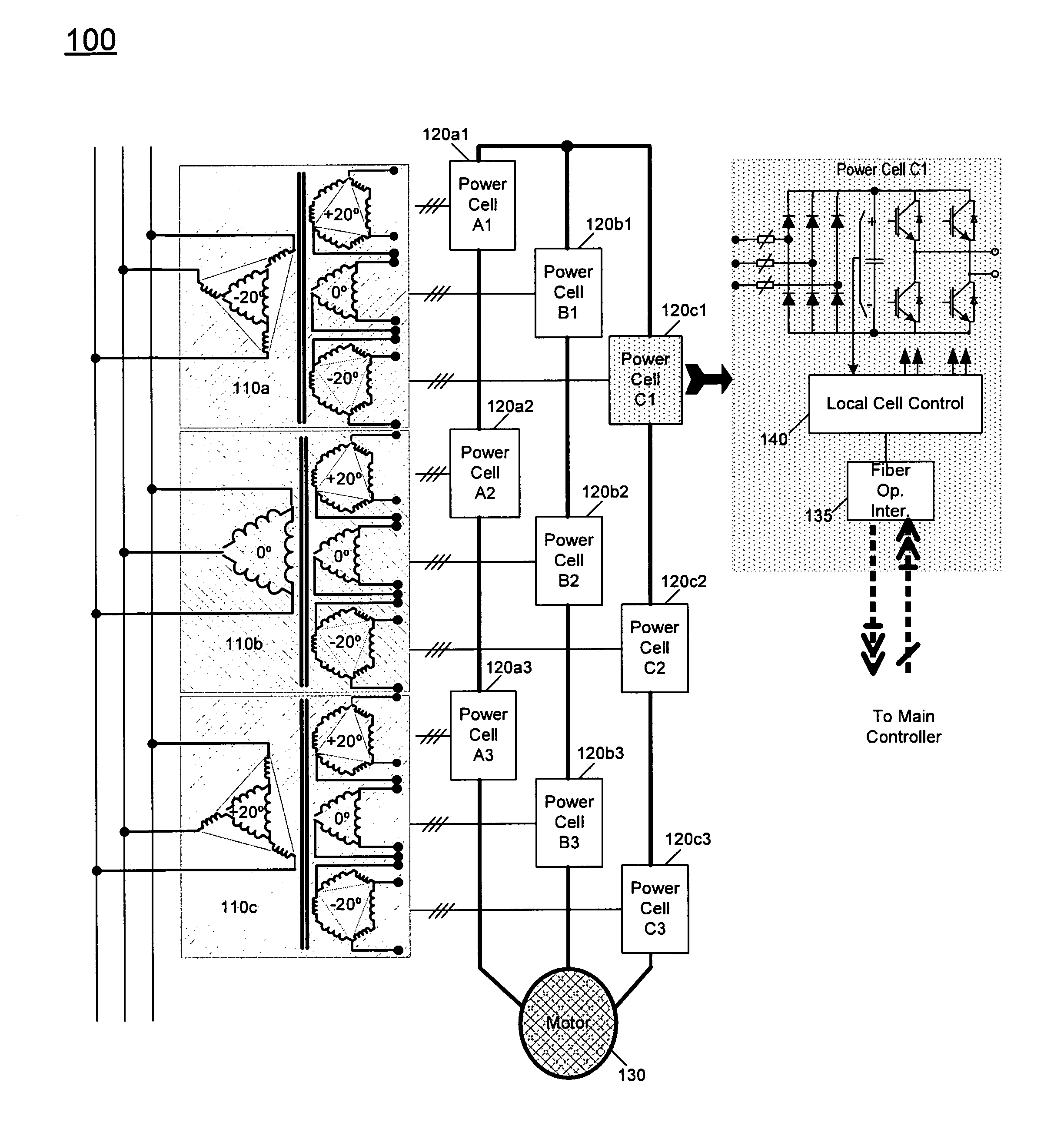
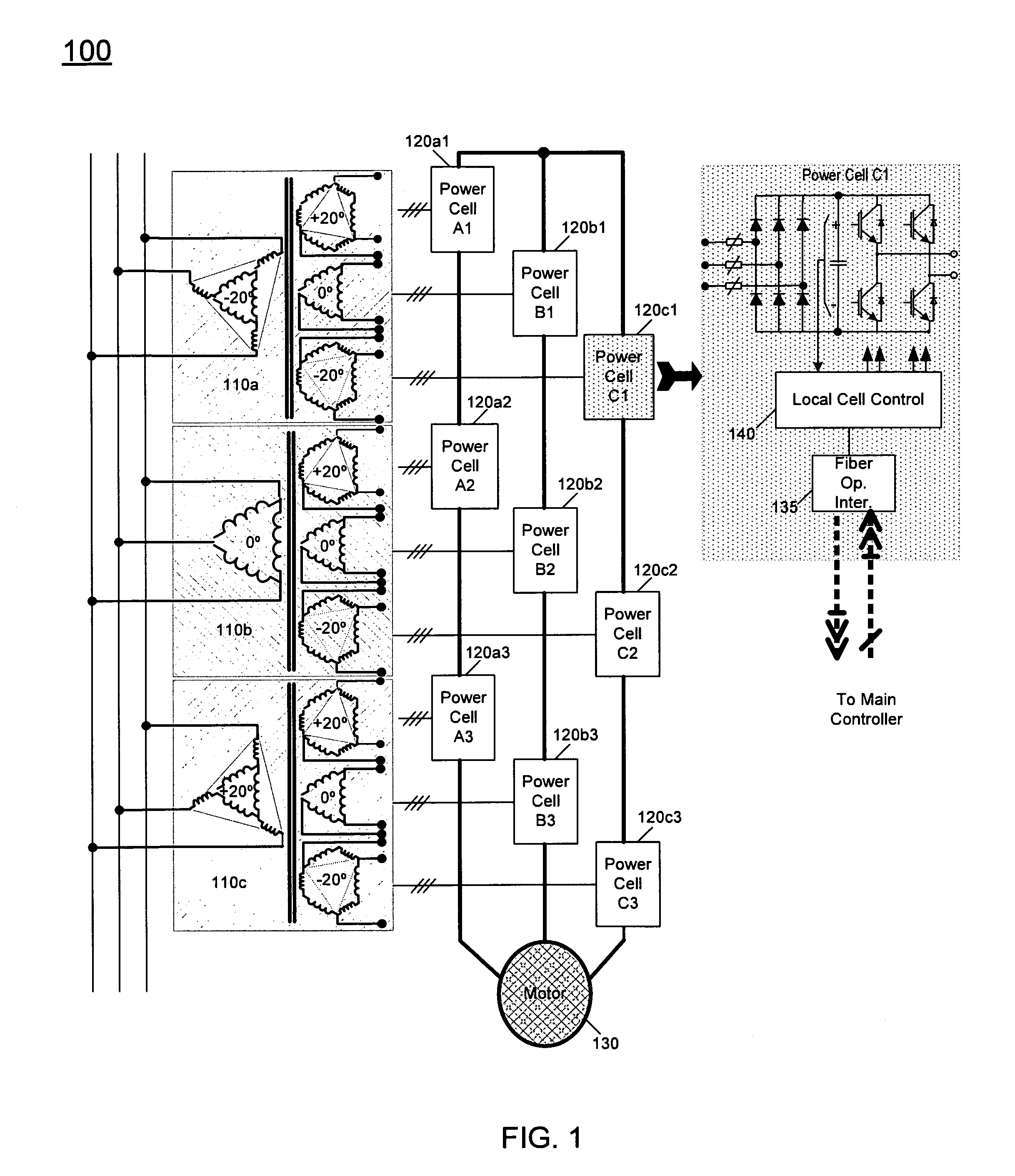
[0020]Referring now to FIG. 1, shown is a block diagram of an inverter in accordance with an embodiment of the present invention. More specifically, FIG. 1 shows an implementation of a cascaded medium voltage inverter for a three-phase motor. As shown in FIG. 1, inverter 100 may include modular transformers 110a-110c with passive phase shifting, realized by both phase ...


PUM


Abstract

A transformer module includes a main primary winding coupled to a first input power source to receive a medium voltage signal, multiple main secondary windings each to couple to a power cell of a drive system, and an auxiliary primary winding coupled to a second input power source to receive a low voltage signal. The auxiliary primary winding can be spatially separated from the main windings to increase leakage inductance. The auxiliary primary winding can be active during a pre-charge operation to pre-charge the power cells.

Description

BACKGROUND[0001]Generally, equipment referred to as a power converter, inverter or drive is used to provide power to another piece of equipment such as a motor. Specifically, such a converter (converter is used generally herein to refer to converters, inverters and drives) is coupled to a utility connection to receive incoming input power such as three-phase AC power. The converter conditions the power to provide a conditioned power signal to the equipment to be powered. In this way, incoming power to the equipment may be of improved efficiency, leading to reduced costs to operate the equipment.[0002]Multi-level power converters have been gaining popularity mainly due to improved power quality, lower switching losses, better electromagnetic compatibility, and higher voltage capability. These improvements in power conversion are achieved by using a multiple voltage step strategy. One common multi-level inverter topology is a series H-bridge inverter, in which multiple H-bridge invert...

Claims


Application Information

Patent Timeline
Patent Type & Authority Patents(United States)
IPC IPC(8): H02J1/10
CPCH01F27/385H02M5/458H02M7/49H02P13/06H02P25/16
Inventor ABOLHASSANI, MEHDIKEISTER, THOMASSKORCZ, ALEXEDWARDS, RYANLEDEZMA, ENRIQUE
Owner TECO WESTINGHOUSE MOTOR
Learn More