Transmission line resonator, high-frequency filter using the same, high-frequency module, and radio device
a technology of transmission line resonators and high-frequency filters, applied in the field of high-frequency filters and a, can solve problems such as substantial insertion loss of transmission characteristics
- Summary
- Abstract
- Description
- Claims
- Application Information
AI Technical Summary
Benefits of technology
Problems solved by technology
Method used
Image
Examples
first exemplary embodiment
[0042]A transmission line type resonator is described in accordance with a first exemplary embodiment of the present invention referring to the drawings.
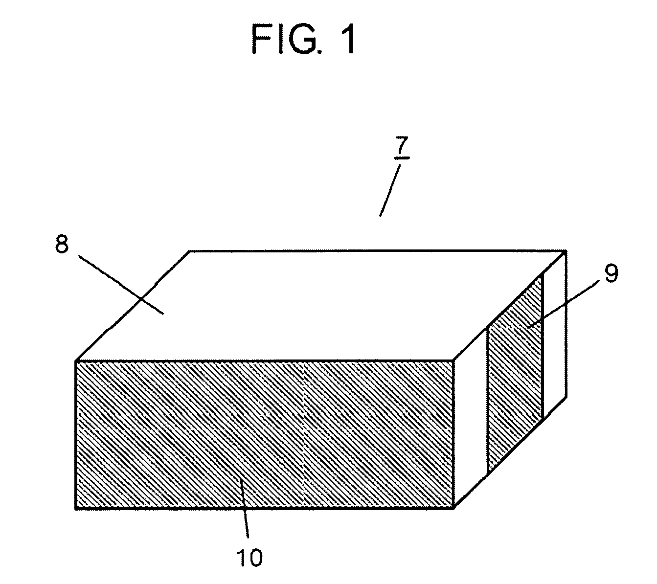
[0043]FIG. 1 shows the appearance of transmission line type resonator in the first embodiment.
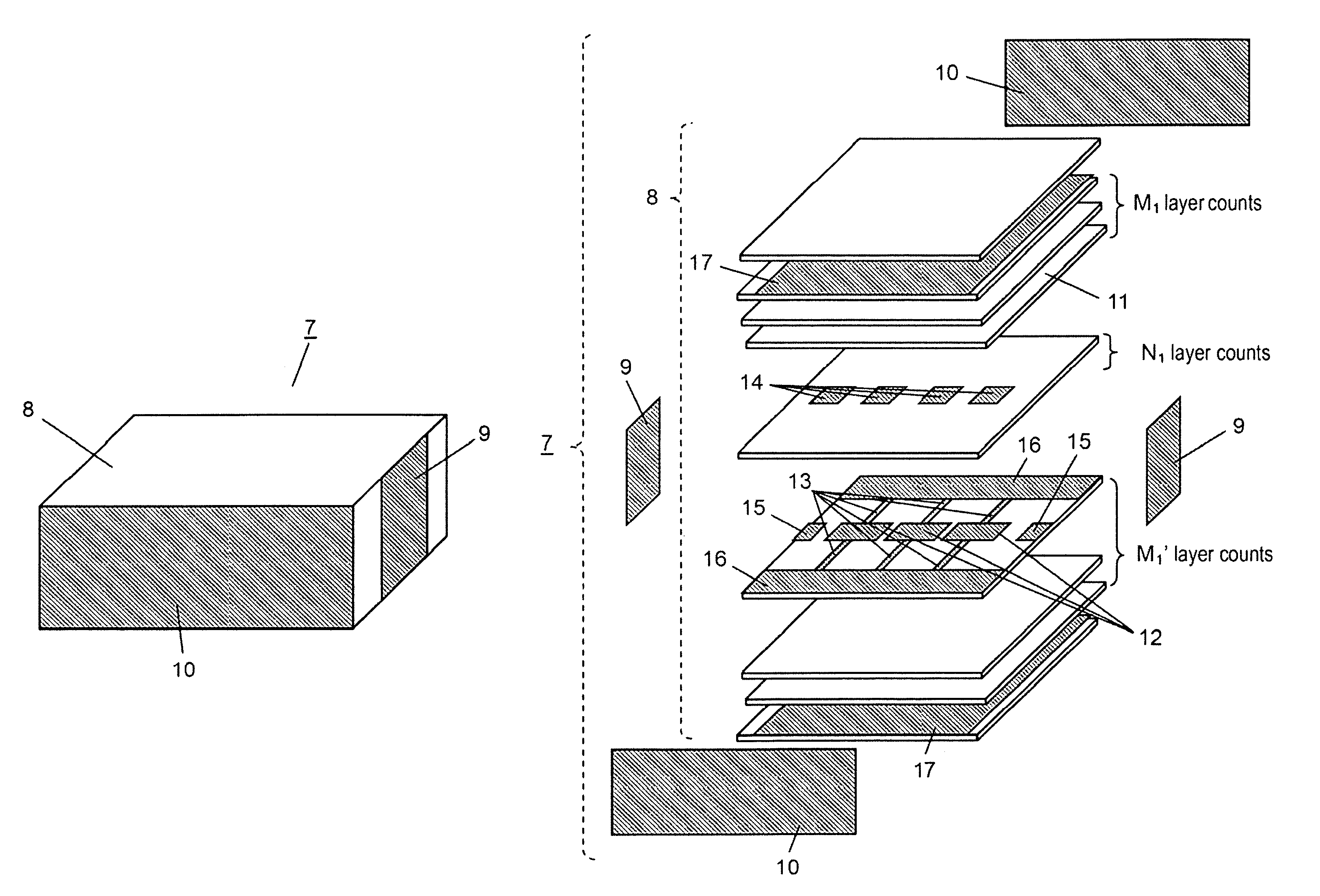
[0044]Referring to FIG. 1, transmission line type resonator 7 includes laminate body 8, external connection terminal 9 disposed on the end face of laminate body 8, and grounding electrode 10.
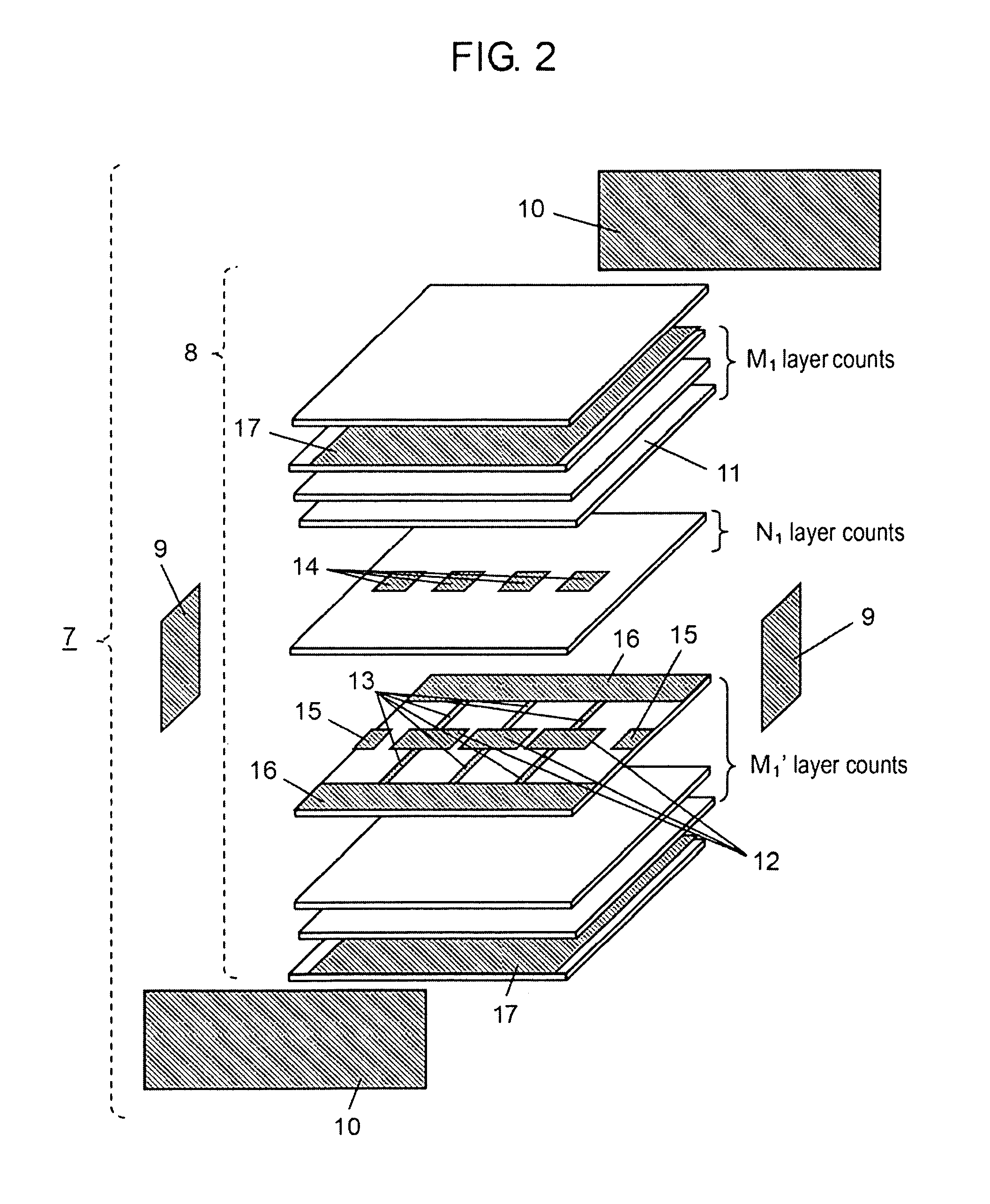
[0045]FIG. 2 is an exploded perspective view of the transmission line type resonator, which is of complex right hand left hand system, according to the first embodiment. Transmission line type resonator 7 of complex right hand left hand system is formed by laminating a plurality of dielectric sheets 11 made of either a low temperature co-fired ceramic material or a resin material. On a certain dielectric sheet 11, a plurality of line electrodes 12 is provided in a straight line arrangement with an optional space between each other.
[0046]Line electrode 1...
second exemplary embodiment
[0065]A transmission line type resonator of complex right hand left hand system is described in the structure in accordance with a second embodiment of the present invention. Unless otherwise described, those portions designated with the same numerals as in the first embodiment have the same structure and operate the same as the transmission line type resonator of the first embodiment; so, description of such portions is eliminated. FIG. 9 shows an exploded perspective view of a transmission line type resonator of complex right hand left hand system in accordance with the second embodiment. FIG. 10 is the cross sectional view, sectioned along the line 10-10.
[0066]Capacitance electrode 14 is eliminated in the second embodiment; instead, line electrode 12 is provided for two layers, with the location shifted so that the respective line electrodes are placed alternately. By so doing, the capacitive coupling is produced between the opposing line electrodes 12.
[0067]The above-described s...
third exemplary embodiment
[0068]The structure of a transmission line type resonator of complex right hand left hand system is described in accordance with a third embodiment of the present invention. Unless otherwise described, those portions designated with the same numerals as in the first embodiment have the same structure and operate the same as the transmission line type resonator of the first embodiment; so, description of such portions is eliminated. FIG. 11 shows an exploded perspective view of transmission line type resonator 7 of complex right hand left hand system in accordance with the third embodiment. FIG. 12 shows the cross sectional view, sectioned along the line 12-12.
[0069]In the third embodiment, line electrode 12 is grounded to shield pattern electrode 17 by means of via hole electrode 18, instead of connection pattern electrode 13. Via hole electrode 18 works as parallel inductor LL. Grounding pattern electrode 16 can be eliminated. The above structure enables reduction in the width of t...
PUM
 Abstract
Description
Claims
Application Information
 - R&D
- Intellectual Property
- Life Sciences
- Materials
- Tech Scout
- Unparalleled Data Quality
- Higher Quality Content
- 60% Fewer Hallucinations
Browse by: Latest US Patents, China's latest patents, Technical Efficacy Thesaurus, Application Domain, Technology Topic, Popular Technical Reports.
© 2025 PatSnap. All rights reserved.Legal|Privacy policy|Modern Slavery Act Transparency Statement|Sitemap|About US| Contact US: help@patsnap.com


