
Vehicle body reinforcing structure

a technology for reinforcing structures and vehicles, applied in vehicle arrangements, roofs, transportation and packaging, etc., can solve the problems of limiting the endurance strength of the body panel and the like against the load received from the outer frame member, and achieving high rigidity. , the effect of improving the transmission efficiency of load and facilitating the fastening of the members

Inactive Publication Date: 2012-06-26
SUZUKI MOTOR CORP
View PDF4 Cites 9 Cited by
  • Summary
  • Abstract
  • Description
  • Claims
  • Application Information

AI Technical Summary

Benefits of technology

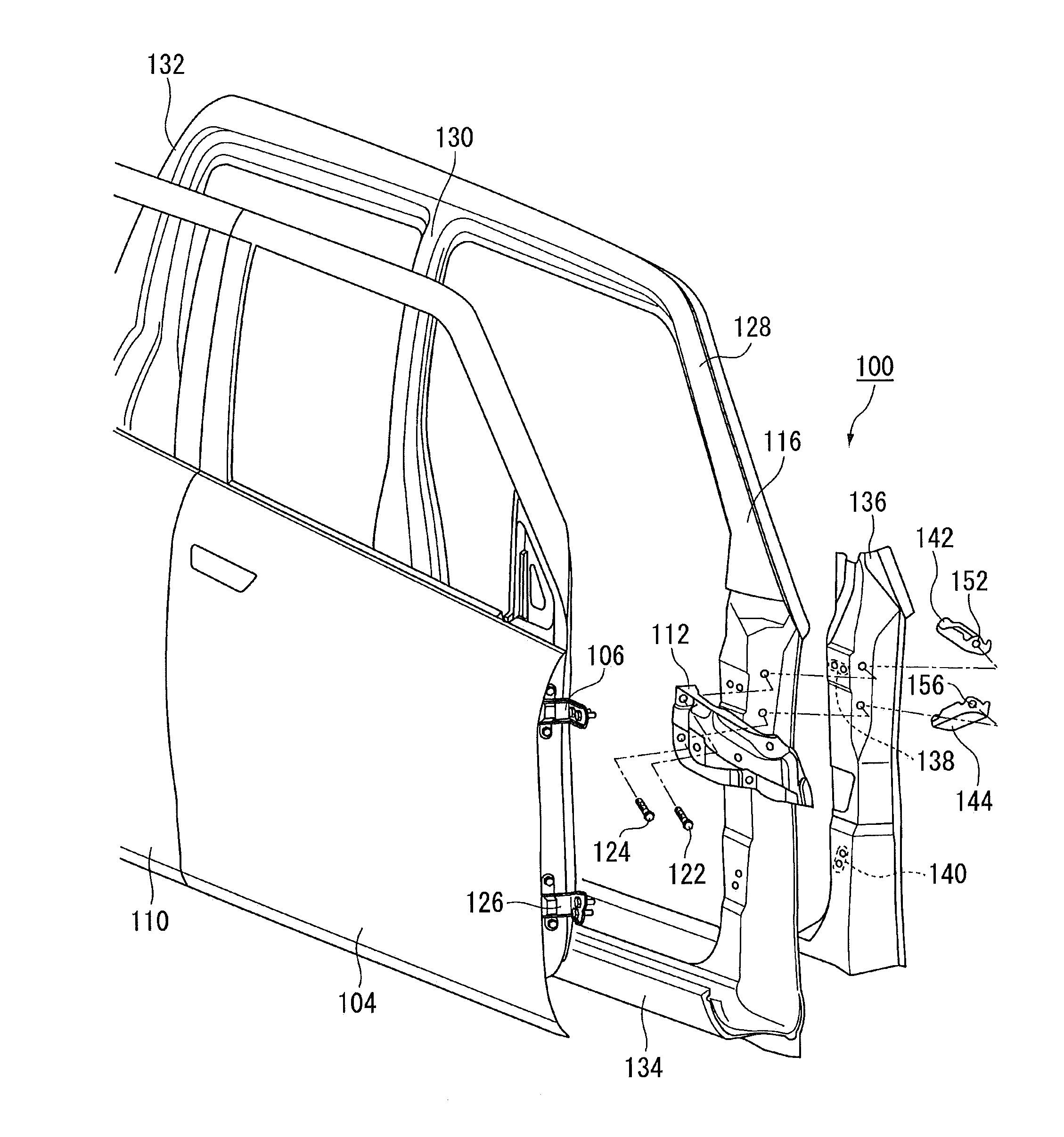
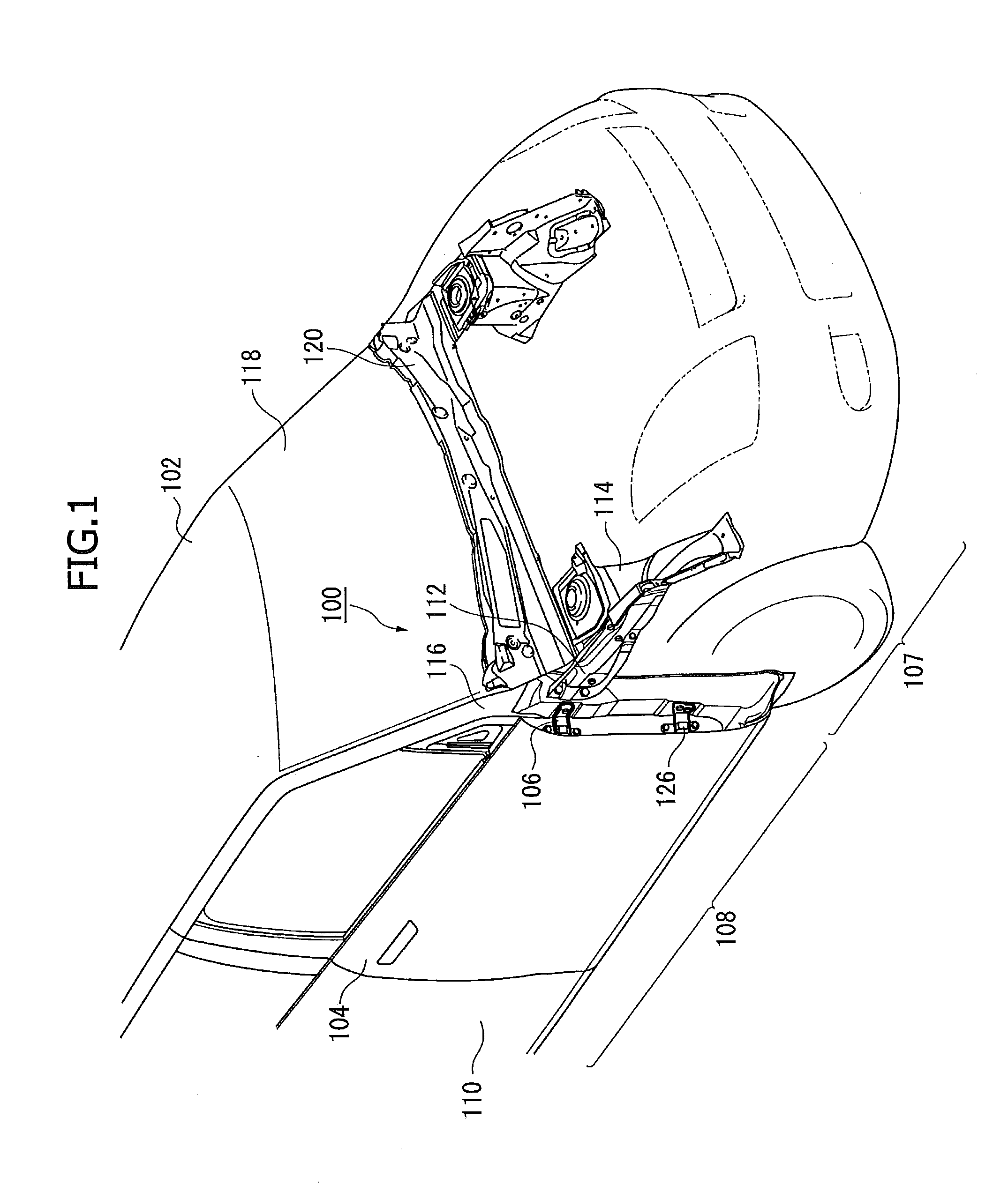
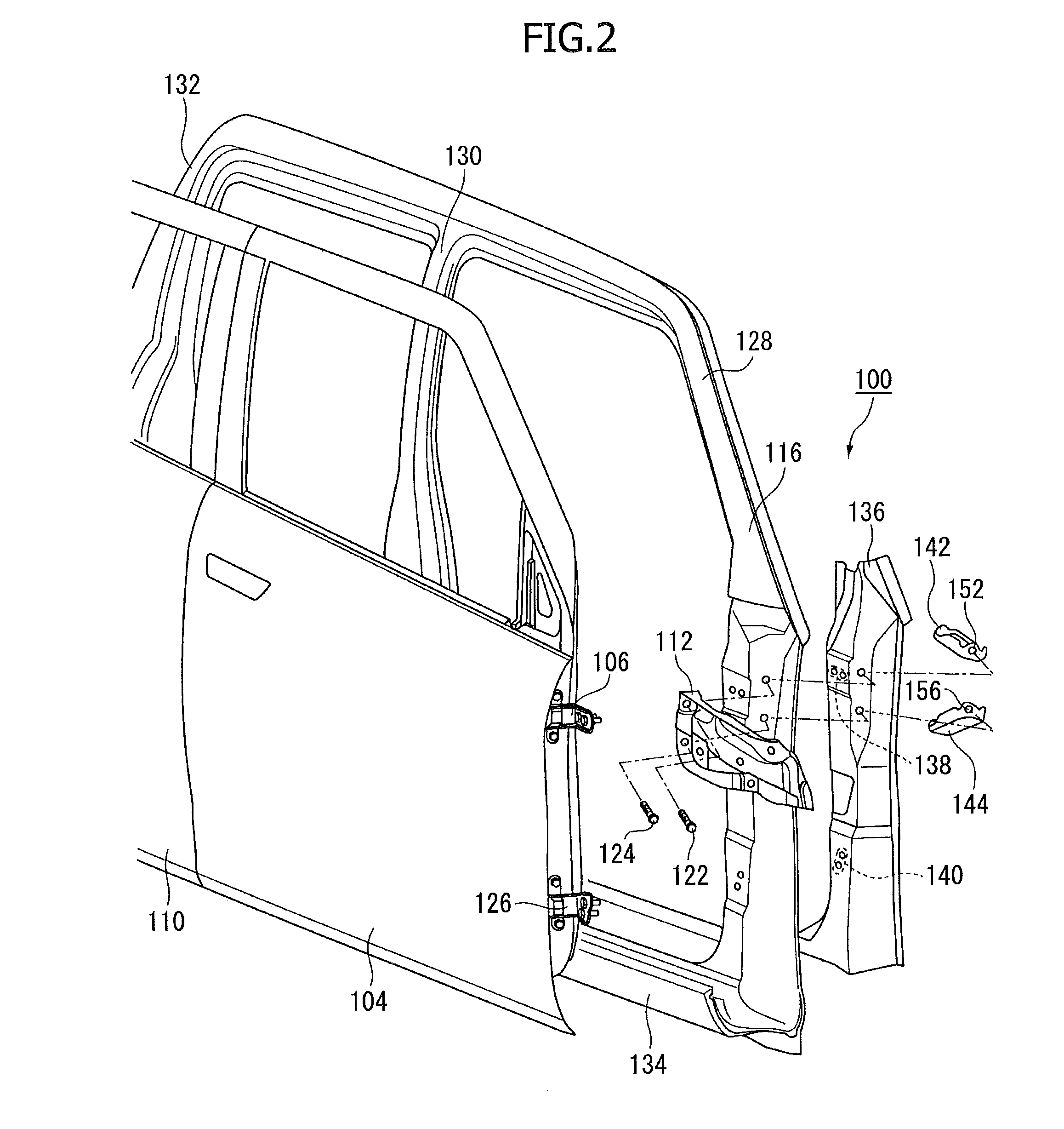
The present invention provides a vehicle body reinforcing structure that improves the structural durability of the side body against a load applied from the front and connects the front body and side body more firmly. The structure includes a side wall member that is curved and attached to the front body via a door hinge, a connecting member that attaches the side wall member to the front portion of the vehicle body, and a reinforcing member that reinforces the side wall member and is curved along its length. A brace member is also included that reinforces the reinforcing member and is attached to the reinforcing member, connecting member, side wall member, and front door. The brace member has a plane surface part that extends in the vehicle body longitudinal direction and is attached to the reinforcing member and front door. The vehicle body reinforcing structure improves the load bearing capacity of the side body and ensures the structural durability of the vehicle body against damage from the front.

Problems solved by technology

However, in such a curved configuration, it is difficult to think that a high rigidity can be achieved in the curved direction, so that the endurance strength of the body panel and the like against the load received from the outer frame member may be restricted structurally.

Method used


Image

  • Vehicle body reinforcing structure
  • Vehicle body reinforcing structure
  • Vehicle body reinforcing structure

Examples


Embodiment Construction

[0024]The present invention now will be described more fully hereinafter in which embodiments of the invention are provided with reference to the accompanying drawings. This invention may, however, be embodied in many different forms and should not be construed as limited to the embodiments set forth herein; rather, these embodiments are provided so that this disclosure will be thorough and complete, and will fully convey the scope of the invention to those skilled in the art.

[0025]The terminology used in the description of the invention herein is for the purpose of describing particular embodiments only and is not intended to be limiting of the invention. As used in the description of the invention and the appended claims, the singular forms “a”, “an” and “the” are intended to include the plural forms as well, unless the context clearly indicates otherwise.

[0026]Unless otherwise defined, all technical and scientific terms used herein have the same meaning as commonly understood by ...


PUM


Abstract

There is provided a vehicle body reinforcing structure capable of improving the structural durability of a side body against a load applied from the front and capable of connecting a front body and the side body more firmly to each other. In the vehicle body reinforcing structure including a side wall member 116 which is curved so as to be convex toward the vehicle body outside, and to which a front door is attached via a door hinge; a connecting member 112 for connecting the side wall member to the front portion of a vehicle body; and a reinforcing member 136 that is attached to the vehicle body inside of the side wall member along the up-and-down direction, is curved along the curved side wall member, and reinforces the side wall member, there are provided brace members (an upper brace member 142 and a lower brace member 144) each of which has a plane surface part, fits to the curved inner surface of the reinforcing member, and is configured so that the plane surface part extends in the vehicle body longitudinal direction; and bolts 122 and 124 for fastening the connecting member, the side wall member, the reinforcing member, and the brace member together.

Description

CROSS-RELATED APPLICATIONS[0001]This application claims priority from Japanese Patent Application No. 2010-104514; filed Apr. 28, 2010, the disclosure of which is incorporated herein by reference in its entirety.BACKGROUND OF THE INVENTION[0002]The present invention relates to a vehicle body reinforcing structure between a front body and a side body of a vehicle body.[0003]Generally, the vehicle body of a motor vehicle excluding openable portions such as an engine hood, doors, and the like, is called a body shell. The body shell can be divided broadly into a front body constituting the front portion of vehicle body, a rear body constituting the rear portion thereof, a side body constituting a side wall thereof, and an underbody constituting the lower surface thereof.[0004]Among these bodies, the front body is the front end in the travel direction of the vehicle body, and is a portion liable to be subjected to a load from the front during running. When the front body is subjected to ...

Claims


Application Information

Patent Timeline
Patent Type & Authority Patents(United States)
IPC IPC(8): B62D25/02
CPCB62D25/04B62D21/09B62D25/088
Inventor HATTORI, NOBUHIKO
Owner SUZUKI MOTOR CORP
Learn More