
Sunvisor for vehicle

a technology for sun visors and vehicles, applied in the direction of roofs, superstructures, monocoque constructions, etc., can solve the problems of pin breakage, abnormal sound or noise, cracks in the boss, etc., and achieve the effect of improving the durability of the structure for joining the shells that constitute the sun visor body

Active Publication Date: 2012-05-17
KYOWA SANGYO
View PDF16 Cites 9 Cited by
  • Summary
  • Abstract
  • Description
  • Claims
  • Application Information

AI Technical Summary

Benefits of technology

[0007]The present invention provides a sun visor for a vehicle in which the durability of a structure for joining shells that constitute a sun, visor body is improved.
[0020]As described above, in the sun visor for a vehicle, the durability of the structure for joining the shells that constitute the sun visor body is improved.

Problems solved by technology

In the vehicular sun visor of the above type, when the shells of the sun visor body are joined together, a crack may be formed in a boss due to stress produced when a pin is press-fitted into the boss.
Also, abnormal sound or noise may occur due to stress applied to the sun visor body in a condition where the crack is formed.
On the other hand, when a pin is press-fitted into a boss, radial stress is applied to the pin, and the pin may be inclined by an amount equal to or larger than a given amount, which may result in breakage of the pin.

Method used


Image

  • Sunvisor for vehicle
  • Sunvisor for vehicle
  • Sunvisor for vehicle

Examples


first embodiment

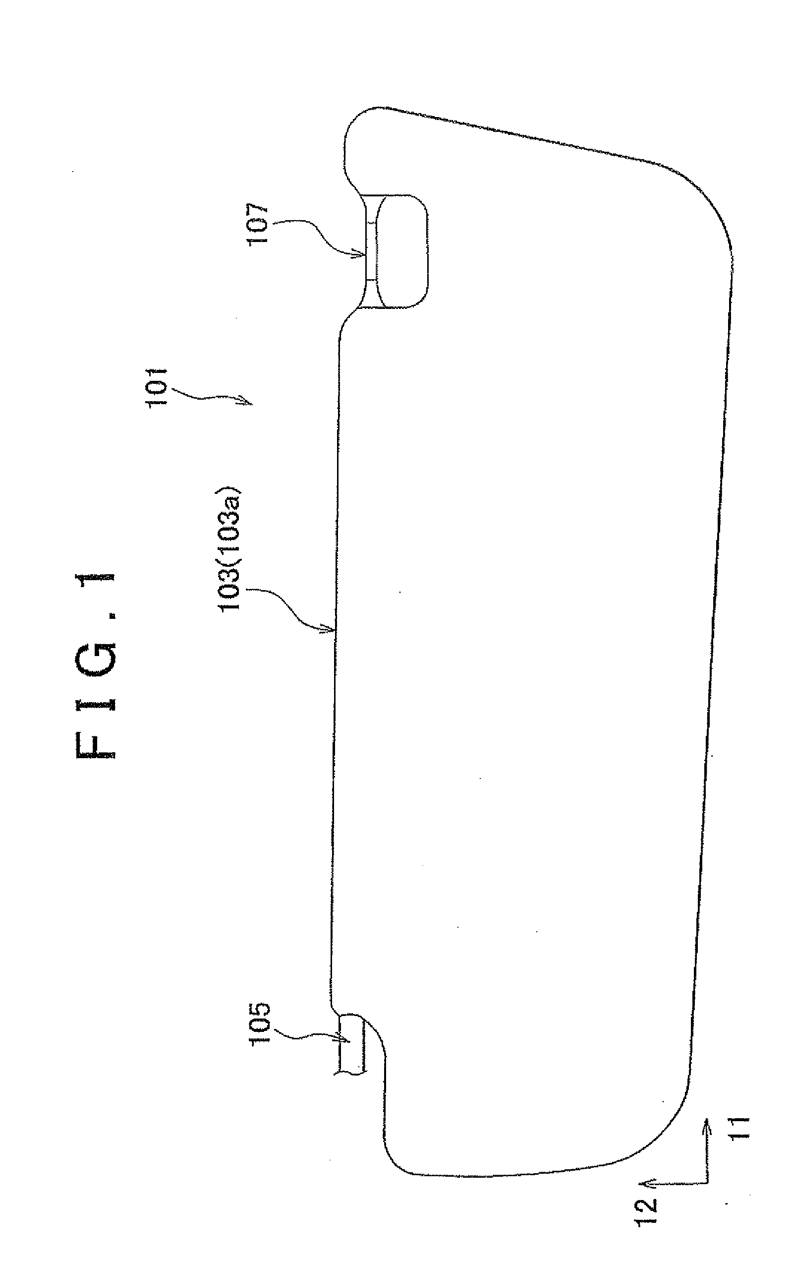
[0034]A sun visor for a vehicle according to the invention will be described in detail with reference to the drawings. In FIG. 1, the overall construction of the vehicular sun visor 101 is illustrated in a flat view.

[0035]The vehicular sun visor 101 of the first embodiment is installed in the vicinity of the top of the windshield of the vehicle. As shown in FIG. 1, the vehicular sun visor 101 includes a sun visor body 103, a pivot shaft 105, a support shaft 107, and a mounting bracket (not shown).

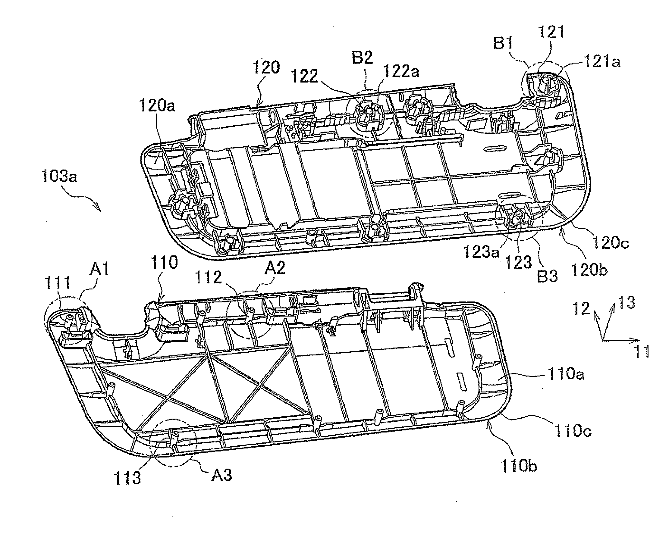
[0036]The sun visor body 103 forms the outline or profile of the vehicular sun visor 101. The sun visor body 103 includes a shell member 103a, and a skin that covers the outer surface of the shell member 103a. The shell member 103a is a generally rectangular member having a suitable thickness. As shown in FIG. 1, the shell member 103a has long sides that extend in a first direction 11, and short sides that extend in a second direction 12 that intersects at substantially right angles with th...

second embodiment

[0066]When joining of the first shell 110 and the second shell 120 is completed, as shown in FIG. 12, the second wall 115 of the first shell 110 and the first walls 124 of the second shell 120 abut on each other while intersecting with each other. Namely, the top edge portion 115a of the second wall 115 abuts on the top edge portions 124a of the first walls 124. With the first walls 124 thus abutting on the second wall 115, the first shell 110 is positioned relative to the second shell 120 in the direction in which the pin 111 is press-fitted. In the second embodiment, in particular, the top edge portion 115a of the second wall 115 of the first shell 110 functions as a mating face that mates with the top edge portions 124a of the first walls 124 of the second shell 120, and the second wall 115 also cooperates with the first walls 114 of the pin 111 to function as the above-mentioned inclination restricting portion. The second wall 115 of the first shell 110 and the first wails 124 o...


PUM


Abstract

A sun visor for a vehicle has a sun visor body including a first shell and a second shell. The first shell includes a pin, and the second shell includes a boss having an insert hole. Further, a first reinforcing portion that extends in a given direction from at least one of the pin and the boss and a second reinforcing portion that extends in a direction intersecting with the direction of extension of the first reinforcing portion are provided.

Description

INCORPORATION BY REFERENCE[0001]The disclosure of Japanese Patent Application No. 2010-254052 filed on Nov. 12, 2010 including the specification, drawings and abstract is incorporated herein by reference in its entirety.BACKGROUND OF THE INVENTION[0002]1. Field of the Invention[0003]The invention relates to a sun visor for a vehicle.[0004]2. Description of the Related Art[0005]In a known arrangement of a sun visor for a vehicle, two shells into which a sun visor body is divided in the thickness direction are joined to each other via a suitable joining or coupling portion(s), to provide the sun visor body. In a sun visor for a vehicle as disclosed in Japanese Patent Application Publication No 2005-47322, for example, an arrangement in which bosses provided on one of the shells are press-fitted into pins provided on the other shell is used as the joining portions.SUMMARY OF THE INVENTION[0006]In the vehicular sun visor of the above type, when the shells of the sun visor body are joine...

Claims


Application Information

Patent Timeline
Patent Type & Authority Applications(United States)
IPC IPC(8): B60J3/00
CPCB60J10/085B60J3/0278B60J10/86
Inventor FUKATSU, TSUYOSHI
Owner KYOWA SANGYO
Learn More