
Self supporting implant in a human body and method for making the same without capsular contracture

a self-supporting, human body technology, applied in the field of self-supporting and self-forming implants, can solve the problems of limiting affecting the natural movement of the implant, so as to achieve the effect of reducing volume and/or enhancing shap

Inactive Publication Date: 2012-06-12
TECHNO INVESTMENTS
View PDF26 Cites 30 Cited by
  • Summary
  • Abstract
  • Description
  • Claims
  • Application Information

AI Technical Summary

Benefits of technology

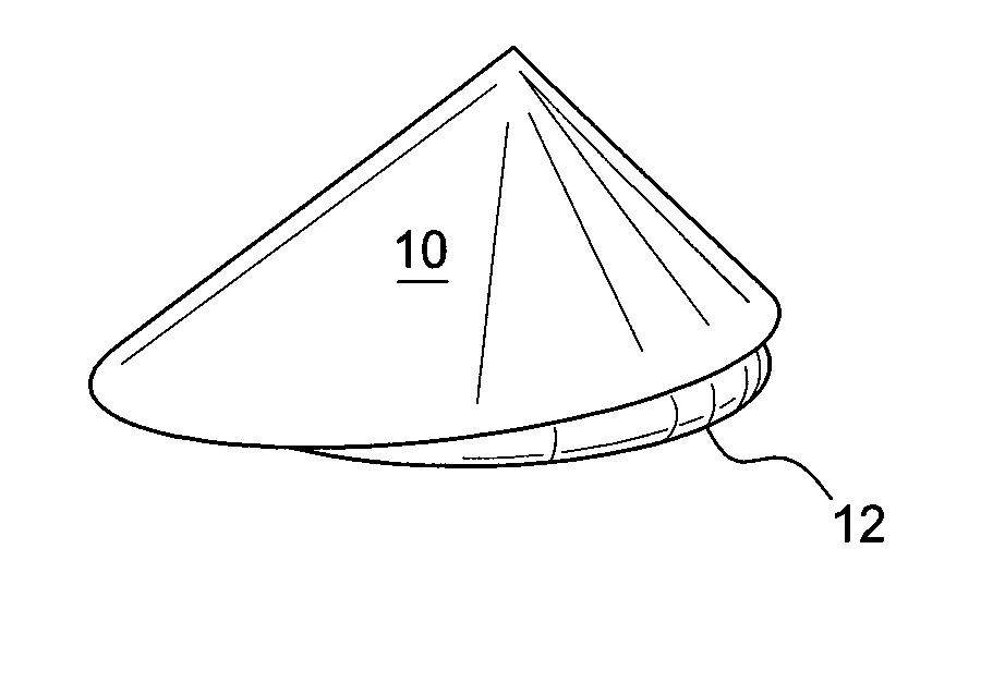
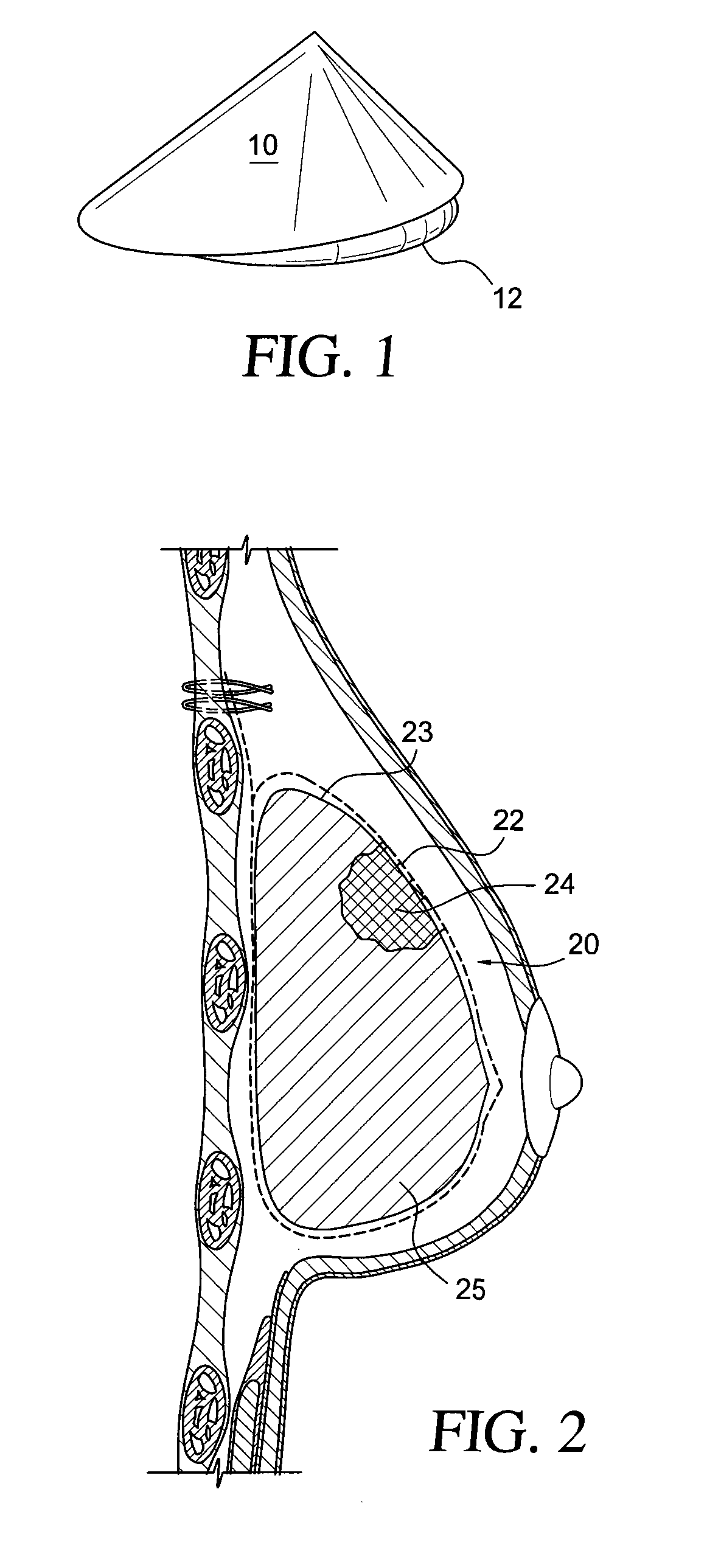
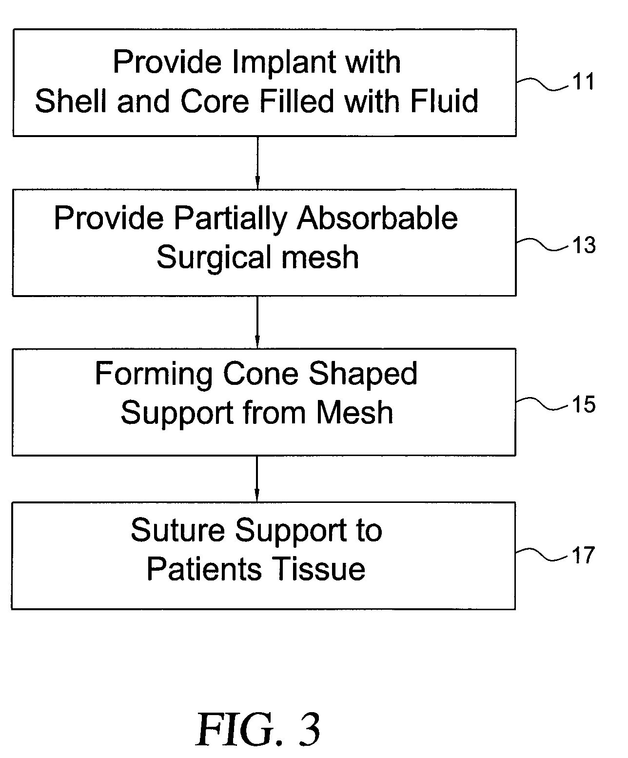
[0009]The invention also contemplates a method for forming and supporting a breast implant including the steps of providing a breast implant and a mass of non-absorbable or partially absorbable light weight surgical mesh. The surgical mesh is formed into a generally cone shaped support and the implant, a smooth sided, non-absorbable shell is disposed in the cone shaped support. In a preferred embodiment of the invention the base of the cone is enclosed with a sheet of the mesh material so that the implant, preferably having a smooth surface, is fully covered by the mesh support that is in close proximity thereto and the mesh support or an extension thereof is surgically attached to the patient's tissue to thereby provide an internal bra-like support. Also, because of the flexibility of the mesh material, the cone shaped mesh in combination with the generally round or slightly pear shaped implant takes on the natural form of a breast. Ideally the mesh support pouch is used with an adjustable implant. With an adjustable gel implant, the implant can be expanded to further enhance the shape and / or reduced in volume subsequent to at least partial healing to thereby provide a slight space between the implant and the support. Providing a space between the implant and support overcomes problems associated with capsular contracture.

Problems solved by technology

However, texturing the surface of implants has limitations.
For example, the textured surface does not work in a number of cases.
Further, the implant itself may adhere to the tissue thus limiting the natural movement of the implant.

Method used


Image

  • Self supporting implant in a human body and method for making the same without capsular contracture
  • Self supporting implant in a human body and method for making the same without capsular contracture
  • Self supporting implant in a human body and method for making the same without capsular contracture

Examples


Embodiment Construction

[0017]As illustrated in FIG. 1 a generally cone shaped support member 10 is formed from a mass or sheet of medical mesh as for example ULTRAPRO®, partially absorbable material from Ethicon Inc., a Johnson and Johnson company located in Langhorne, Pa. This mesh which is used in the preferred embodiment of the invention is constructed of polypropylene, about 75% (non-absorbable) and poliglecaprone, about 25% (absorbable), monofilament material. It is also contemplated that a non-absorbable mesh made of nylon or the like may be used in place of the partially absorbable mesh.

[0018]The absorbable portion of the mesh may encompass the whole surface, or part of the surface i.e. the upper portion can be predominantly absorbable while the lower part is predominantly non absorbable, this will allow a sling of support to remain inferiorly while the upper portion is absorbed. The direction of the elasticity can also be configured so as to enhance shape of a round implant on expansion, i.e. if t...


PUM


Abstract

A self supporting breast implant includes a generally cone shaped partially absorbable medical mesh support member and a silicone shell defining a hollow core that is preferably filled or partially filled with a silicone gel. The support member is made of a polypropolene / poliglecaprone monofilament and may be attached to a patient's tissue by sutures or by absorbable hooks. A textured outer surface or shell is formed around the relatively smooth implant or inner shell and the inner shell is reduced in size to provide a small space between the inner shell and the outer shell to eliminate or at least minimize the adverse effects of capsular contraction.

Description

[0001]This application is a Continuation-in-Part of co-pending U.S. application Ser. No. 12 / 552,353, filed Sep. 2, 2009, herein incorporated by reference.FIELD OF THE INVENTION[0002]This invention relates to a self supporting and self forming implant and to a method for forming and supporting a breast implant in a human body.BACKGROUND FOR THE INVENTION[0003]Implants for breast augmentation and / or reconstruction are well known and have been in use for over 20 years. During that period, the implants have undergone a number of significant changes. For example, early implants had a smooth outer shell; however, as developments progressed the smooth shell was replaced with a textured surface. This was done in an effort to reduce problems associated with capsular contraction and to support a natural or pear shaped implant in position.[0004]One approach to the use of a textured surface is disclosed in my co-pending U.S. patent application Ser. No. 12 / 169,000 filed on Jul. 8, 2008, that is ...

Claims


Application Information

Patent Timeline
Patent Type & Authority Patents(United States)
IPC IPC(8): A61F2/12
CPCA61F2/12
Inventor BECKER, HILTON
Owner TECHNO INVESTMENTS
Learn More